Direct Digital Controller
Direct Digital Controller fw 4.013 – Ed. 01/2013 69
4.4.1.4 Machine configuration
Before performing these operations, make sure that all the built-in S61 electronic boards have been
configured, i.e. have had an ID (identifier = network address) assigned to them and have been assigned to a
plant.
Moreover, check that the correct group of belonging has been assigned to every unit: Base plant part or
Splitting plant part (see programming manual, sheet S61).
In the presence of one or more RB100 or RB200 devices, also check that they have been configured (see
“RB100 Installation and Use Booklet” Code D-LBR468 or “RB200 Installation and Use Booklet” Code D-
LBR632) according to the type of device used.
Finally ensure that all units and any RB100 or RB200 devices are switched on when the Direct Digital
Controller (DDC) is switched on.
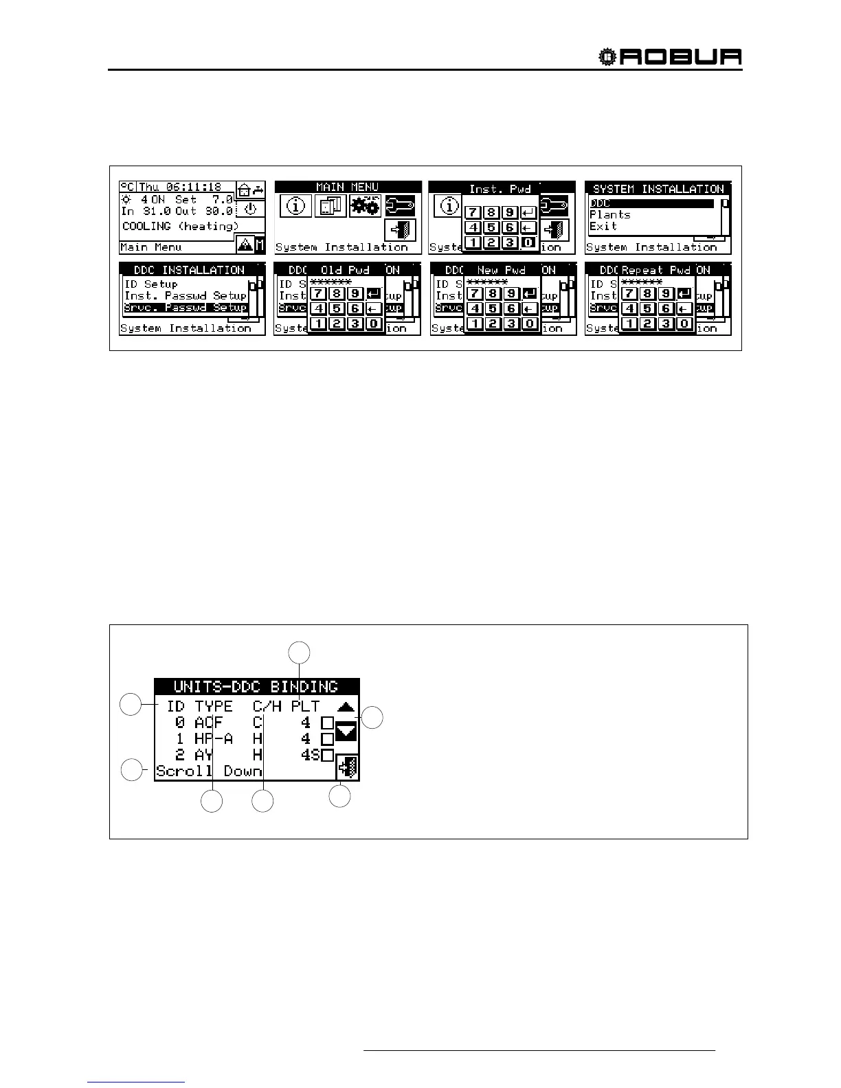
Description of the screen.
Figure 17 shows an example screen from the Machine configuration menu.
Figure 17– EXAMPLE OF MACHINE CONFIGURATION MENU SCREEN
Table 5 shows all types of units and plant parts with a short description. For more information on the
management of third party units (only with RB200) and plant parts also refer to the “Installation and use
booklet for RB100 (code D-LBR468) and the “RB100 Applications Manual (code D-LBR467)”, or the
“Installation and Use Booklet for RB200” (Code D-LBR632) and “Applications Manual” (Code D-LBR630),
according to the device used.
The DDC deduces which plant or plants it must manage from the plants on which the units assigned to the
DDC itself are configured.
E
C
D
B
G
F
KEY:
A Unit identification number (network ID).
B Type of Robur or third party unit, or type of plant part managed by
RB100 or RB200 device(s); see Table 5
C Function of the unit or plant part; C chilled water production; H hot
water production; C/H alternate production of chilled/hot water (not for
third party units).
D Identification number of system on which the unit is installed. Letter
“S” indicates that the group to which the unit or the plant part belongs
is the separable system.
E Scroll arrows for viewing the units.
F Exit screen
G Text describing function represented by the icon highlighted by the
cursor