Do you have a question about the Rockford Fosgate Punch P5002 and is the answer not in the manual?
| Brand | Rockford Fosgate |
|---|---|
| Model | Punch P5002 |
| Category | Amplifier |
| Language | English |
Crucial safety warnings and precautions for installation and operation.
Lists the items included in the product packaging.
Illuminates when unit is on; 'Swirl' indicates output signal level.
Yellow LED indicates short circuit or low impedance; auto-shutdown.
Yellow LED indicates overheating; auto-shutdown for cooling.
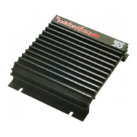
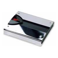
Dissipates heat generated by the amplifier's circuitry.
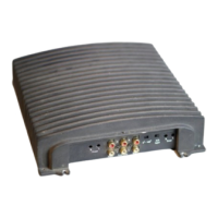
Heavy-duty, nickel-plated clamp connectors for speaker wire.
Boosts low frequency with 45Hz adjustment for road noise.
Input gain control to match source unit output levels.
Built-in 12dB/octave filter, selectable HP, AP, or LP from 40-400Hz.
Industry standard jacks for signal level input, nickel-plated.
Allows daisy-chaining additional amplifiers without extra cables.
Connects for remote turn-on/turn-off with +12V DC.
Nickel-plated connectors for power and ground wire connections.
Easily accessible ATC fuses for failure protection, matching type and rating.
Lists tools needed and essential pre-installation checks and safety rules.
Guidance on where to mount the amplifier for optimal performance and warranty.
Recommendations for ensuring the vehicle's electrical system can handle the amplifier load.
Detailed steps and cautions for connecting the amplifier's wiring.
Diagram and instructions for connecting in a 2-channel stereo configuration.
Diagram and instructions for connecting in a bridged/mono configuration.
Instructions for mounting and installing the remote bass control.
Procedure for setting the amplifier's input gain for optimal volume and signal-to-noise.
How to set the crossover frequency for High Pass, All Pass, or Low Pass modes.
Verifies power, ground, and voltage connections for proper amplifier operation.
Diagnoses issues indicated by the Protect or Thermal status LEDs.
Guides on testing RCA inputs and signal source for audio issues.
Solutions for preventing unwanted popping sounds during amplifier turn-on.
Methods to identify and eliminate engine noise interference in the audio system.