C
Chad HendersonAug 16, 2025
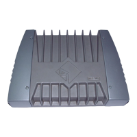
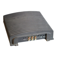
Why my Rockford Fosgate Amplifier does not turn on (Power LED is off)?
- PPeter GuerraAug 16, 2025
If your Rockford Fosgate Amplifier does not turn on and the power LED is off, it could be due to several reasons: * The voltage applied to the REM terminal of the amplifier is not between 10.5 and 15.5 volts, or there is no voltage present. Check the alternator, battery, fuse, and wiring, repairing as necessary. If the voltage exceeds 15.5 volts, have the electrical system inspected by a certified car service center. * The voltage to the B+ terminal of the amplifier is not within the range of 10.5 to 15.5 volts, or there is no voltage present. Check the alternator, battery, fuse, and wiring, and repair if needed. For voltages above 15.5 volts, consult an authorized car service center. * The amplifier might not be properly grounded. Check the wiring and repair as needed.