
M
Mark PierceAug 1, 2025
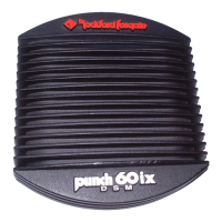
Why does my Rockford Fosgate Punch get too hot?
- RraycruzAug 1, 2025
If your Rockford Fosgate Amplifier is overheating: 1. Ensure the amplifier is properly mounted, allowing heat to rise. Mount the amplifier with the heatsink fins aligned vertically to allow free airflow. Check that the heatsink fins are free of obstructions such as carpet or seats. 2. If the issue persists, verify that the impedance of the overall system is not less than 2R as described on page 14.