68 Rockwell Automation Publication 440R-UM013F-EN-P - July 2021
Chapter 11 Troubleshooting
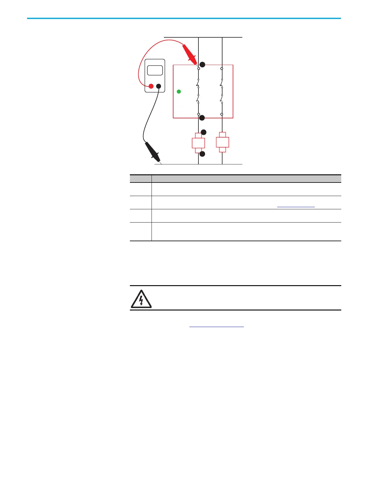
Figure 76 - Measure the Terminal Voltage
Measure the Contact Resistance
If the voltage at terminal 13 is the same as the supply voltage but terminal 14
measures 0V, measure the contact resistance.
Measure the contact resistance to confirm that the relay is not functioning
properly. As shown in Figure 77 on page 69
, remove the power wires to
terminal 13 and set the digital multimeter to ohms. Be sure that the OUT status
indicator is green.
The contact resistance must be less than 1 ohm. If it is not, then the internal
positive-guided relay is not functioning properly, and the GSR safety relay
must be replaced.
Step Description
1
The voltage at 13 must be the same as the supply voltage. If not, check for an open circuit (broken
wire), blown fuse, or tripped circuit breaker.
2
The voltage at 14 must be the same as the supply voltage. If not, the positive-guided relay inside the
GSR safety relay is not closing. Measure the contact resistance; see Figure 77 on page 69
.
3
The voltage at A1 must be the same as the supply voltage. If not, check for an open circuit (broken
wire) between terminal 14 and A1.
4
The voltage at A2 must be zero. If not, check for an open circuit between A1 and the voltage supply
ground connection. If A2 measures zero volts and A1 measures the supply voltage, then K1 is not
operating properly and must be replaced.
SHOCK HAZARD: Turn off power before power connection is removed if +V
supply is greater than 50V.
14
24
+Vs
13
OUT
23
Volts
DMM
K2
A2
A1
1
2
K1
A2
A1
3
4
 Loading...


