72 Rockwell Automation Publication ENET-IN002H-EN-P - August 2017
Appendix D Fiber Cable and LC Connector
Fiber channel power budget at rated BER
(Two connected modules or taps, either the 1756-EN2F
EtherNet/IP fiber module, or 1783-ETAP1F or 1783-
ETAP2F EtherNet/IP fiber taps)
12.8 dB for 62.5/125 μm multimode fiber
9.3 dB for 50/125 μm multimode fiber
Fiber type Glass
62.5/125 μm and 50/125 μm multimode fiber
Simplex or duplex
Jacket type and jacket diameter is dependent on
connector selection
Graded Index (GI) fiber
Per IEC 60794-1-1, IEC 60793-2-10 category A1 fibers
Connector type IEC 61754-20 LC connector, max. insertion loss 0.75 dB per
connection
Channel length, max 2 km (1.24 mi)
(1)
(1) The channel, that is, connectors and cable, must not exceed the allowable power budget.
Allow at least 5.08 cm (2 in.) for the fiber cable bend radius. Contact
the cable manufacturer for more information on the recommended cable
bend radius.
Table 5 - Fiber Cable and LC Connector Specifications
Attribute Value
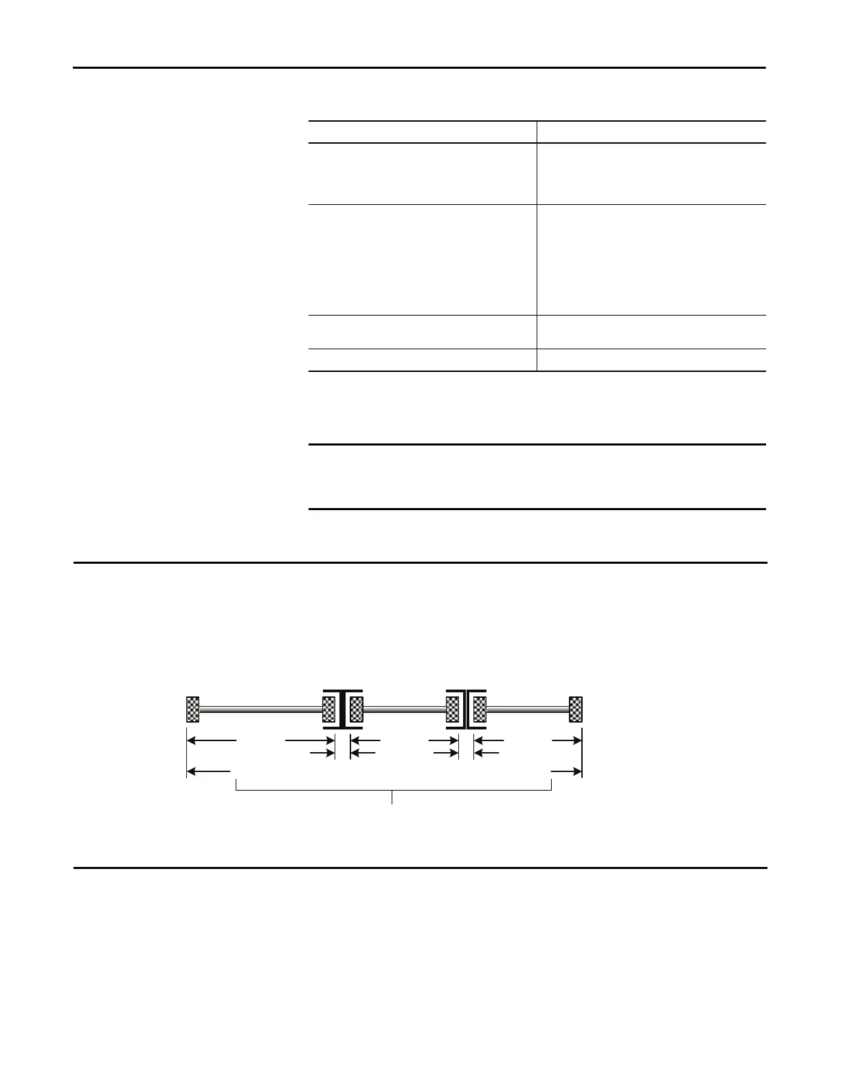
In the example shown here, the channel insertion loss is calculated for an optical channel based on these factors:
• 1 dB/km fiber
• 0.75 dB per adapter
Note that in this example, the end connectors are not factored in the calculations.
ATTENTION: The maximum power budget for this example is 12.8 dB for 62.5/125 μm fiber. Therefore, the channel
insertion loss for the example of 3.5 dB is less than the maximum power budget.
Fiber 1 dB/km Fiber 1 dB/kmFiber 1 dB/km
0.75 dB0.75 dB
1km0.75km 0.25km
0.75 dB 0.75 dB 0.75dB 0.25 dB1 dB
++++
Total channel insertion loss = 3.5 db
 Loading...