10 Publication 1769-UM020A-EN-P - December 2009
Chapter 1 Overview
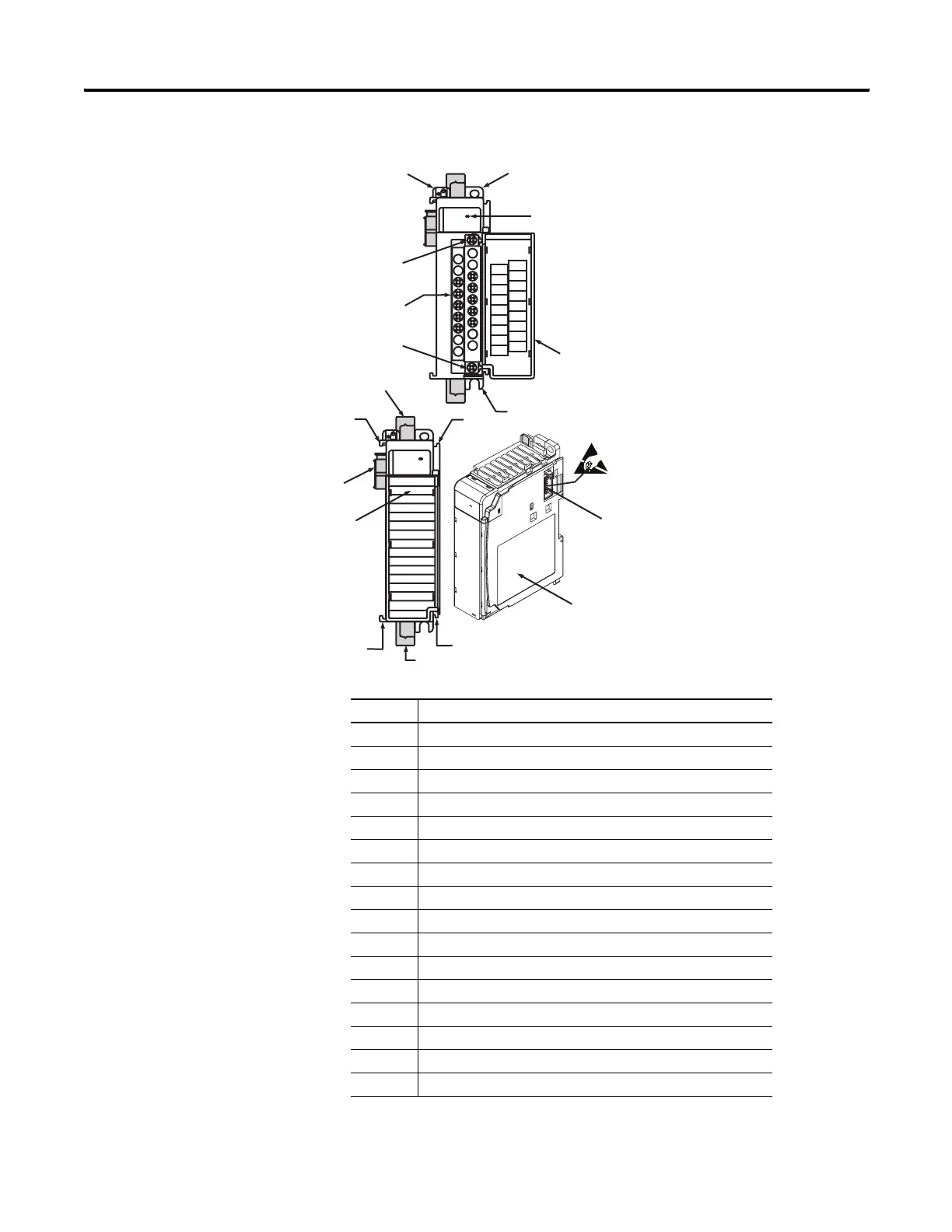
Hardware Features
1769-OF4
DANGER
Do Not Remove RTB Under Power
Unless Area is Non-Hazardous
Ensure Adjacent
Bus Lever is Unlatched/Latched
Before/After
Removing/Inserting Module
I out 3 +
I out 0+
I out 2+
ANLG
Com
ANLG
Com
V out 0 +
V out 2+
V out 1+
V out 3+
I out 1+
OK
Analog
OK
Analog
2a
1
3
10a
10
10b
4
2b
8a
7a
9
7b
8b
7a
5b
6
5a
7b
Item Description
1 Bus lever (with locking function)
2a Upper-panel mounting tab
2b Lower-panel mounting tab
3 Module status indicators
4 Module door with terminal identification label
5a Movable bus connector with female pins
5b Stationary bus connector with male pins
6 Nameplate label
7a Upper tongue-and-groove slots
7b Lower tongue-and-groove slots
8a Upper DIN-rail latch
8b Lower DIN-rail latch
9 Write-on label for user identification tags
10 Removable terminal block (RTB) with finger-safe cover
10a RTB retaining screw
10b RTB retaining screw

 Loading...


