Publication 1769-UM020A-EN-P - December 2009 55
Appendix
B
Module Addressing and Configuration with
MicroLogix 1500 Controller
Introduction
This appendix examines the modules’ addressing scheme and
describes module configuration using RSLogix 500 software and a
MicroLogix 1500 controller.
Module Input Image
The module’s input image file represents status bits and data echo
words. Input word 0 holds the status bits for the analog output
channels. Input words 1…4 hold the data that represents the directed
value of the analog outputs for channels 0…3. These data words are
valid only when the channel is enabled and there are no errors.
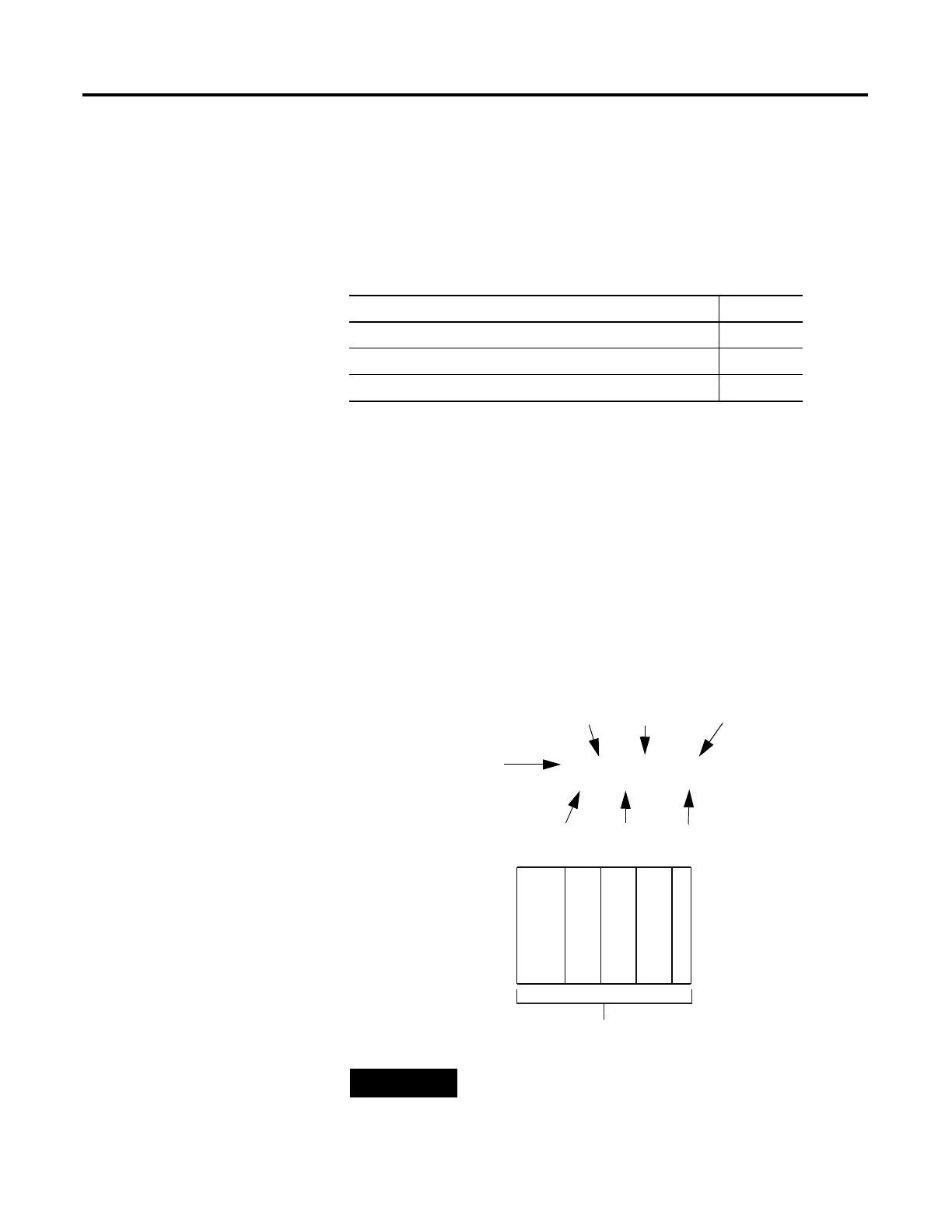
For example, to obtain the general status of channel 2 of the analog
module located in slot 3, use address I:3.0/2.
Topic Page
Module Input Image 55
Module Configuration File 56
Configure Analog I/O Modules in a MicroLogix 1500 System 57
TIP
The end cap does not use a slot address.
I:3.0/2
Input File Type
Slot
Word
Bit
Bit Delimiter
Word Delimiter
Element Delimiter
0123
MicroLogix 1500
Compact I/O
Compact I/O
Compact I/O
End Cap
Slot Number

 Loading...


