6 Rockwell Automation Publication 1794-IN082F-EN-P - October 2022
FLEX I/O EtherNet/IP Adapters Installation Instructions
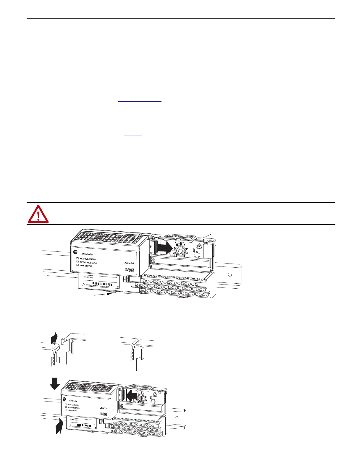
Mount the Adapter on a DIN Rail
Mount the adapter on the DIN rail before installing any terminal bases or I/O modules.
1. Hook the lip on the rear of the adapter (A) onto the top of the 35 x 7.5 mm (1.38 x 0.30 in.) DIN rail (B).
2. Rotate the adapter onto the rail.
3. Press the adapter down onto the DIN rail until flush.
4. DIN rail locking tab (C) snaps into position and lock the adapter to the DIN rail.
5. If the adapter does not lock in place, use a screwdriver or similar device to move the locking tab down while pressing the adapter flush onto the DIN rail: releasing the
locking tab to lock the adapter in place.
6. If necessary, push up on the locking tab to lock.
7. Connect the adapter wiring as shown under Connect Wiring
on page 7.
Mount on a Panel or Wall
To mount the adapter to a panel or wall, see publication 1794-IN135, Panel Mounting Kit, catalog number 1794-NM1/B.
Mount or Replace the Adapter on an Existing System
1. Remove the Ethernet plug-in connector from the bottom of the adapter.
2. Disconnect any adapter wiring that is jumpered to the adjacent terminal base.
3. Disconnect any user power wiring connections to the adapter.
4. Using a screwdriver or similar tool, open the module locking mechanism and remove the module from the base unit to which the adapter is attached.
5. Push the Flexbus connector toward the right side of the terminal base to unplug the backplane connection.
6. Release the DIN rail locking tab (C) and remove the adapter.
Before installing the new adapter, notice the notch on the right rear of the adapter. This notch accepts the hook on the terminal base unit. The notch is open at the bottom.
The hook and adjacent connection point keep the terminal base and the adapter tight together, reducing the possibility of a break in communication over the backplane.
ATTENTION: Verify that the Flexbus connector is completely clear of the adapter. The slide must be completely to the right and the raised spot on
the slide visible.
Locking tab C
Terminal base of I/O module
adjacent to the 1794-AENT adapter.
 Loading...