Rockwell Automation Publication 1794-IN082F-EN-P - October 2022 7
FLEX I/O EtherNet/IP Adapters Installation Instructions
7. Push down and in at the same time to lock the adapter to the DIN rail.
8. When the adapter is locked onto the DIN rail, gently push the Flexbus connector into the adapter to complete the backplane.
9. If the adapter does not lock in place, use a screwdriver or similar device to move the locking tab down while pressing the adapter flush onto the DIN rail: releasing the
locking tab to lock the adapter in place.
If necessary, push up on the locking tab to lock.
10. Reinstall the module in the adjacent terminal base unit.
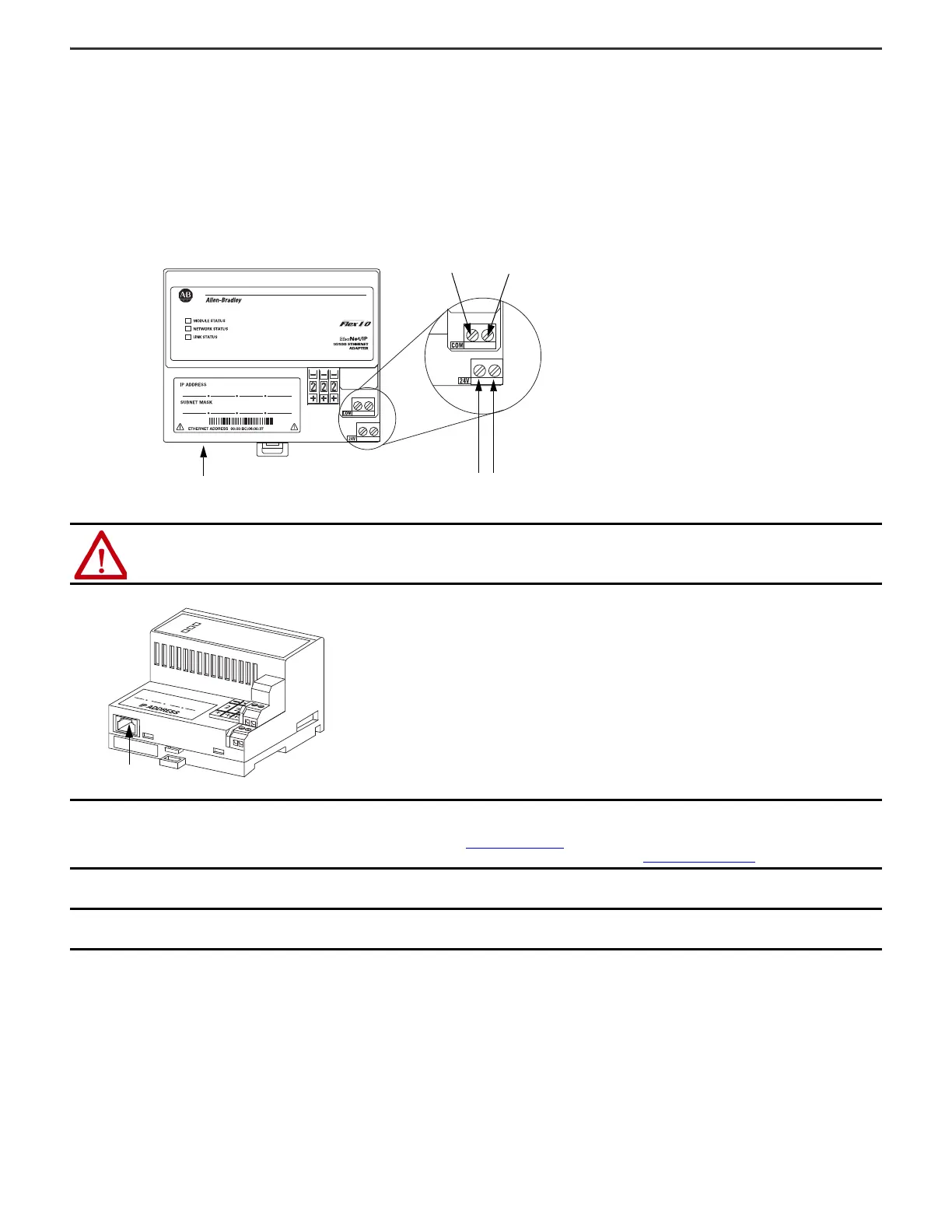
Connect Wiring
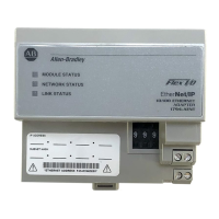
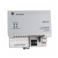
1. Connect the Ethernet network cable to the RJ45 connector (A) on the underside of the adapter.
2. Connect 24V common to the left side of the upper connector, terminal B.
3. Connect +24V DC input power to the left side of the lower connector, terminal C.
4. Use connectors D and E to pass 24V common (D) and 24V DC power (E) to the next module in the series.
WARNING: If you connect or disconnect the communication cable with power applied to the adapter or any device on the network, an electrical arc can occur. This
could cause an explosion in hazardous location installations. Be sure that power is removed or the area is nonhazardous before proceeding.
IMPORTANT
We recommend connecting the module to the network via a 100 MB full-duplex switch, which reduces network collisions and lost packets, and increase
bandwidth. For detailed Ethernet connection information, see these publications:
• EtherNet/IP Performance and Application Guide, available at https://www.odva.org
• Suggestions to Increase the Noise Immunity of the 1794-AENT FLEX I/O EtherNet/IP Adapter System, rok.auto/knowledgebase Technote ID IN20767
IMPORTANT
Do not wire more than 2 conductors on any single terminal.
When connecting wiring, torque terminal screws B, C, D, and E to 0.8 N•m (7 lb•in).
 Loading...