PowerFlex 400P Adjustable Frequency AC Drive Quick Start English-23
A153 [PID Feedback Sel] 0/8 0 = “Analog In 1”
1 = “Analog In 2”
2 = “Comm Port”
3 = “ACT1 - ACT2”
4 = “ACT1 + ACT2”
5 = “ACT1 * ACT2”
6 = “ACT1 / ACT2”
7 = “Min A1, A2”
8 = “Max A1, A2”
0
A154 [PID Prop Gain] 0.00/99.99 0.01 1.00
A155 [PID Integ Time] 0.0/999.9 Secs 0.1 Secs 2.0 Secs
A156 [PID Diff Rate] 0.00/99.99 (1/Secs) 0.01 (1/Secs) 0.00 (1/Secs)
A157 [PID Setpoint] 0.0/100.0% 0.1% 0.0%
A158 [PID Deadband] 0.0/10.0% 0.1% 0.0%
A159 [PID Preload] 0.0/320.0 Hz 0.1 Hz 0.0 Hz
A160 [Process Factor] 0.1/999.9 0.1 30.0
A163 [Auto Rstrt Tries] 0/9 1 0
A164 [Auto Rstrt Delay] 0.0/160.0 Secs 0.1 Secs 1.0 Secs
A165 [Start At PowerUp] 0/1 0 = “Disabled” 1 = “Enabled” 0
A166 [Reverse Disable] 0/1 0 = “Rev Enabled” 1 = “Rev Disabled” 0
A167 [Flying Start En] 0/1 0 = “Disabled” 1 = “Enabled” 0
A168 [PWM Frequency] 2.0/8.0, 10.0 kHz 0.1 kHz 4.0 kHz
A169 [PWM Mode] 0/1 0 = “Space Vector” 1 = “2-Phase” 1
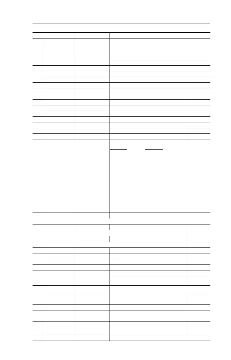
A170 [Boost Select] 0/15 Settings in % of base voltage. 4
Only active when A125 [Torque Perf Mode] is
set to 0 “V/Hz”.
Frames C-F
Frames G-H
0 = “Custom V/Hz” 0 = “Custom V/Hz”
1 = “30.0, VT” 1 = “30.0, VT”
2 = “35.0, VT” 2 = “35.0, VT”
3 = “40.0, VT” 3 = “40.0, VT”
4 = “45.0, VT” 4 = “45.0, VT”
5 = “0.0, no IR” 5 = “0.0, no IR”
6 = “0.0” 6 = “0.0”
7 = “2.5, CT” 7 = “0.2”
8 = “5.0, CT” 8 = “0.5”
9 = “7.5, CT” 9 = “0.8”
10 = “10.0, CT” 10 = “1.0”
11 = “12.5, CT” 11 = “2.0”
12 = “15.0, CT” 12 = “3.0”
13 = “17.5, CT” 13 = “4.0”
14 = “20.0, CT” 14 = “5.0”
15 = “Kepco” 15 = “Kepco”
A171
[Start Boost] 0.0/25.0%
1.1% 2.5%
Only active when A170 [Boost Select] and L361 [Torque Perf Mode] are set to “0”.
A172
[Break Voltage] 0.0/100.0%
0.1% 25.0%
Only active when A170 [Boost Select] and L361 [Torque Perf Mode] are set to “0”.
A173
[Break Frequency] 0.0/320.0 Hz
0.1 Hz 15.0 Hz
Only active when A170 [Boost Select] and L361 [Torque Perf Mode] are set to “0”.
A174 [Maximum Voltage] 20/Rated Volts 1 VAC Rated Volts
A175 [Slip Hertz @ FLA] 0.0/10.0 Hz 0.1 Hz 2.0 Hz
A176 [DC Brake Time] 0.0/99.9 Secs 0.1 Secs 0.0 Secs
A177 [DC Brake Level] 0.0/(Drive Amps × 1.5) 0.1 Amps Amps × 0.05
A178 [DC Brk Time@Strt] 0.0/99.9 Secs 0.1 Secs 0.0 Secs
A179
A180
[Current Limit 1]
[Current Limit 2]
0.0/(Drive Amps × 1.5) 0.1 Amps Amps × 1.1
A181 [Motor OL Select] 0/2 0 = “No Derate” 1 = “Min Derate”
2 = “Max Derate”
0
A182 [Drive OL Mode] 0/3 0 = “Disabled”
1 = “Reduce CLim”
2 = “Reduce PWM”
3 = “Both-PWM 1st”
3
A183 [SW Current Trip] 0.0/(Drive Amps × 1.8) 0.1 Amps 0.0 (Disabled)
A184 [Load Loss Level] 0.0/Drive Amps 0.1 Amps 0.0 (Disabled)
A185 [Load Loss Time] 0/9999 Secs 1 Secs 0 (Disabled)
A186 [Stall Fault Time] 0/5 0 = “60 Seconds”
1 = “120 Seconds”
2 = “240 Seconds”
3 = “360 Seconds”
4 = “480 Seconds”
5 = “Flt Disabled”
0
A187 [Bus Reg Mode] 0/1 0 = “Disabled” 1 = “Enabled” 1
No. Parameter Min/Max Display/Options Default
22P-QS001C-EN-P.fm Page 23 Thursday, March 30, 2017 5:55 PM
 Loading...


