English-22 PowerFlex 400P Adjustable Frequency AC Drive Quick Start
T091 [Wake Sel] 0/13 0 = “AI1 > WakLvl”
1 = “AI1 < WakLvl”
2 = “AI2 > WakLvl”
3 = “AI2 < WakLvl”
4 = “CFrq>WakLvl”
5 = “CFrq<WakLvl”
6 = “FB-SP>WakLvl”
7 = “SP-FB>WakLvl”
8 = “AI1 > WakDev”
9 = “AI1 < WakDev”
10 = “AI2 > WakDev”
11 = “AI2 < WakDev”
12 = “CFrq>WakDev”
13 = “CFrq<WakDev”
0
No. Parameter Min/Max Display/Options Default
Communications Group Parameters
No. Parameter Min/Max Display/Options Default
C102 [Comm Format] 0/9 0 = “RTU 8-N-1”
1 = “RTU 8-E-1”
2 = “RTU 8-O-1”
3 = “RTU 8-N-2”
4 = “RTU 8-E-2”
5 = “RTU 8-O-2”
6 = “MetaSys N2”
7 = “P1 8-N-1”
8 = “P1 8-E-1”
9 = “P1 8-O-1”
0
Power to drive must be cycled before any
changes will affect drive operation.
C103 [Comm Data Rate] 0/5 0 = “1200”
1 = “2400”
2 = “4800”
3 = “9600”
4 = “19.2K”
5 = “38.4K”
3
C104 [Comm Node Addr] 1/247 1 100
C105 [Comm Loss Action] 0/5 0 = “Fault”
1 = “Coast Stop”
2 = “Stop”
3 = “Continu Last”
4 = “Run Preset 0”
5 = “Kypd Inc/Dec”
0
C106 [Comm Loss Time] 0.1/60.0 Secs 0.1 Secs 5.0 Secs
C107 [Comm Write Mode] 0/1 0 = “Save” 1 = “RAM Only” 0
C108 [Start Source 2] 0/6 0 = “Keypad”
1 = “3-Wire”
2 = “2-Wire”
3 = “2-W Lvl Sens”
4 = “2-W Hi Speed”
5 = “Comm Port”
6 = “2-W Lvl/Enbl”
3
Sets the control scheme used to start the drive.
C109 [Speed Ref 2] 0/5 0 = “Drive Keypad”
1 = “InternalFreq”
2 = “Analog In 1”
3 = “Analog In 2”
4 = “Preset Freq”
5 = “Comm Port”
2
Advanced Program Group Parameters
No. Parameter Min/Max Display/Options Default
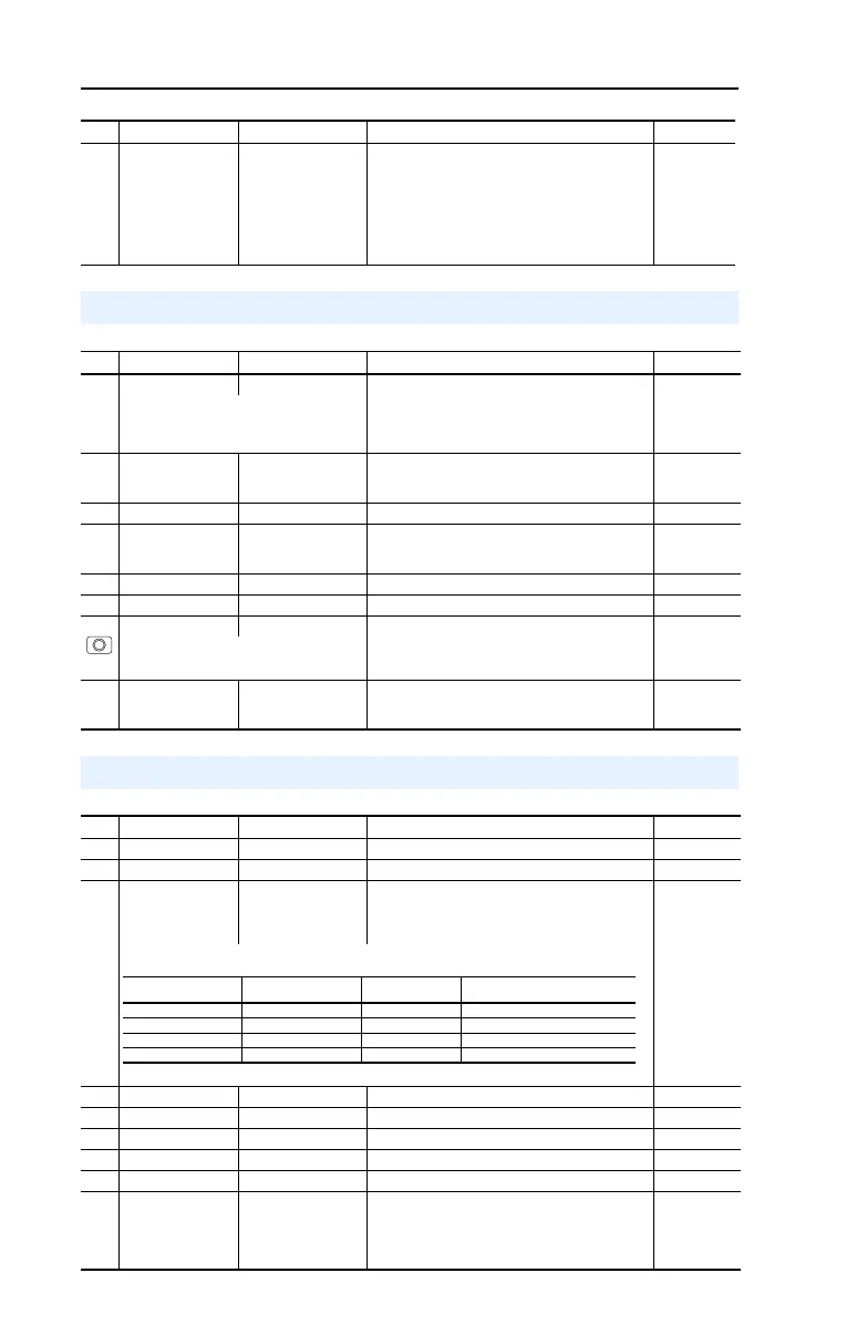
A141 [Purge Frequency] 0.0/320.0 Hz 0.1 Hz 5.0 Hz
A142 [Internal Freq] 0.00/320.00 Hz 0.01 Hz 60.00 Hz
A143
A144
A145
A146
[Preset Freq 0]
(1)
[Preset Freq 1]
[Preset Freq 2]
[Preset Freq 3]
0.0/320.0 Hz 0.1 Hz 0.0 Hz
5.0 Hz
10.0 Hz
20.0 Hz
(1)
To activate [Preset Freq 0] set P038 [Speed Reference] to option 4.
A147 [Accel Time 2] 0.00/600.00 Secs 0.01 Secs 30.00 Secs
A148 [Decel Time 2] 0.00/600.00 Secs 0.01 Secs 30.00 Secs
A149 [S Curve %] 0/100% 1% 20%
A150 [PID Trim Hi] 0.0/320.0 Hz 0.1 Hz 60.0 Hz
A151 [PID Trim Lo] 0.0/320.0 Hz 0.1 Hz 0.0 Hz
A152 [PID Ref Sel] 0/8 0 = “PID Disabled”
1 = “PID Setpoint”
2 = “Analog In 1”
3 = “Analog In 2”
4 = “Comm Port”
5 = “Setpnt, Trim”
6 = “A-In 1, Trim”
7 = “A-In 2, Trim”
8 = “Comm, Trim”
0
Input State of Digital In 1
(I/O Terminal 05)
Input State of Digital In 2
(I/O Terminal 06)
Frequency Source Accel / Decel Parameter Used
(2)
0 0 [Preset Freq 0] [Accel Time 1] / [Decel Time 1]
1 0 [Preset Freq 1] [Accel Time 1] / [Decel Time 1]
0 1 [Preset Freq 2] [Accel Time 2] / [Decel Time 2]
1 1 [Preset Freq 3] [Accel Time 2] / [Decel Time 2]
(2)
When a Digital Input is set to “Accel 2 & Decel 2”, and the input is active, that input overrides the settings in this table.
22P-QS001C-EN-P.fm Page 22 Thursday, March 30, 2017 5:55 PM
 Loading...


