44 Rockwell Automation Publication CC-QS034C-EN-P - March 2015
Chapter 2 System Validation
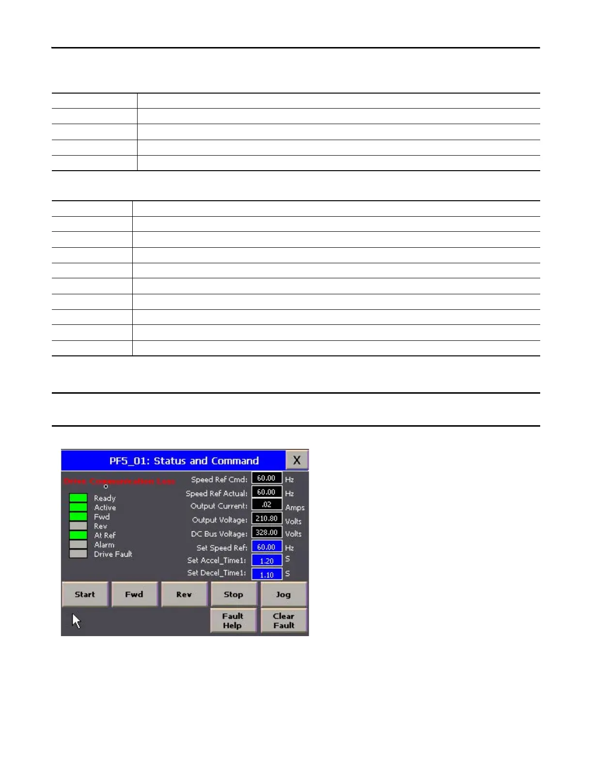
If the controller loses communication with a drive, then a Drive Communication Loss banner appears.
Table 4 - Drive Status
Speed Ref Cmd Value of the active frequency command in Hertz. Shows the commanded frequency even if the drive is not running.
Speed Ref Actual Value of the drive frequency present at T1, T2, T3 (U, V, W), in Hertz.
Output Current Value of the current present at T1, T2, T3 (U, V, W), in amperes.
Output Voltage Value of the voltage present at T1, T2, T3 (U, V, W), in volts.
DC Bus Voltage Value of the present DC bus voltage level, in volts.
Table 5 - Drive Command and Configuration
Set Speed Ref Set the speed reference of the drive by entering a value from 0 to 60.00.
Set Accel_Time1 Set the acceleration time of the drive from 00.01…600.0 seconds.
Set Decel_Time1 Set the deceleration time of the drive from 00.01…600.0 seconds.
Start button Press to start the drive.
Fwd button Press to set the drive direction to forward.
Rev button Press to set the drive direction to reverse.
Stop button Press to stop the drive.
Jog button Press to jog the drive (this button is active only when the drive is stopped).
Clear Fault button Press to clear any drive fault.
Fault Help Press to go to the Fault Help screen, to find more troubleshooting information on an active fault error.
Any drive status values that are shown on this screen during this condition are invalid because the controller cannot
communicate with the drive to update the values.

 Loading...


