1-16 Installation/Wiring
PowerFlex 40 Adjustable Frequency AC Drive FRN 1.xx - 7.xx User Manual
Publication 22B-UM001I-EN-E
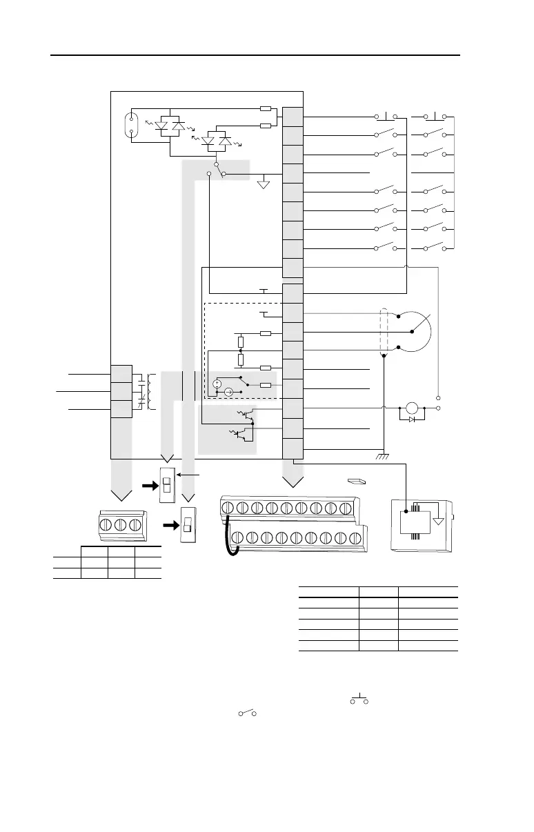
Figure 1.5 Control Wiring Block Diagram
(1)
Important: I/O Terminal 01 is always a coast to stop
input except when P036 [Start Source] is set to
“3-Wire” or “Momt FWD/REV” control. In three wire
control, I/O Terminal 01 is controlled by P037 [Stop
Mode]. All other stop sources are controlled by P037
[Stop Mode].
Important: The drive is shipped with a jumper installed between I/O Terminals 01 and 11. Remove
this jumper when using I/O Terminal 01 as a stop or enable input.
(2)
Two wire control shown. For three wire control use a momentary input on I/O Terminal 02 to
command a start. Use a maintained input for I/O Terminal 03 to change direction.
(3)
When using an opto output with an inductive load such as a relay, install a recovery diode parallel
to the relay as shown, to prevent damage to the output.
(4)
When the ENBL enable jumper is removed, I/O Terminal 01 will always act as a hardware enable,
causing a coast to stop without software interpretation.
04
05
06
07
01
02
03
08
09
11
12
13
14
15
16
17
18
19
Digital Common
Digital Input 1
Digital Input 2
Digital Input 3
Stop
(1)(4)
Start/Run FWD
(2)
Direction/Run REV
Digital Input 4
Opto Common
R1
R2
R3
Relay N.O.
Relay Common
Relay N.C.
+24V DC
+10V DC
0-10V (or ±10V) Input
Analog Common
4-20mA Input
Analog Output
Opto Output 1
Opto Output 2
RS485 Shield
+24V
+10V
Typical
SNK Wiring
Typical
SRC Wiring
1
RS485
(DSI)
R1 R2 R3
SNK
SRC
0-10V
0-20mA
01 02 03 04 05
11 12 13 14 15
06 07 08 09
16 17 18 19
(1)
Enable Jumper
(4)
30V DC
50mA
Non-inductive
Common
24V
ENBL
Enable
(4)
Jumper
(3)
Pot must be
1-10k ohm
2 Watt Min.
0-10V
0/4-20mA
Analog Output Select
SRCSNK
30V DC 125V AC 240V AC
Resistive 3.0A 3.0A 3.0A
Inductive 0.5A 0.5A 0.5A
P036 [Start Source] Stop I/O Terminal 01 Stop
Keypad Per P037 Coast
3-Wire Per P037 Per P037
(4)
2-Wire Per P037 Coast
Momt FWD/REV Per P037 Per P037
(4)
RS485 Port Per P037 Coast
22B-UM001.book Page 16 Tuesday, May 30, 2017 5:22 PM
 Loading...


