11 12 13 14 15 16 17 18 19 20 21 22
23 24 25 26
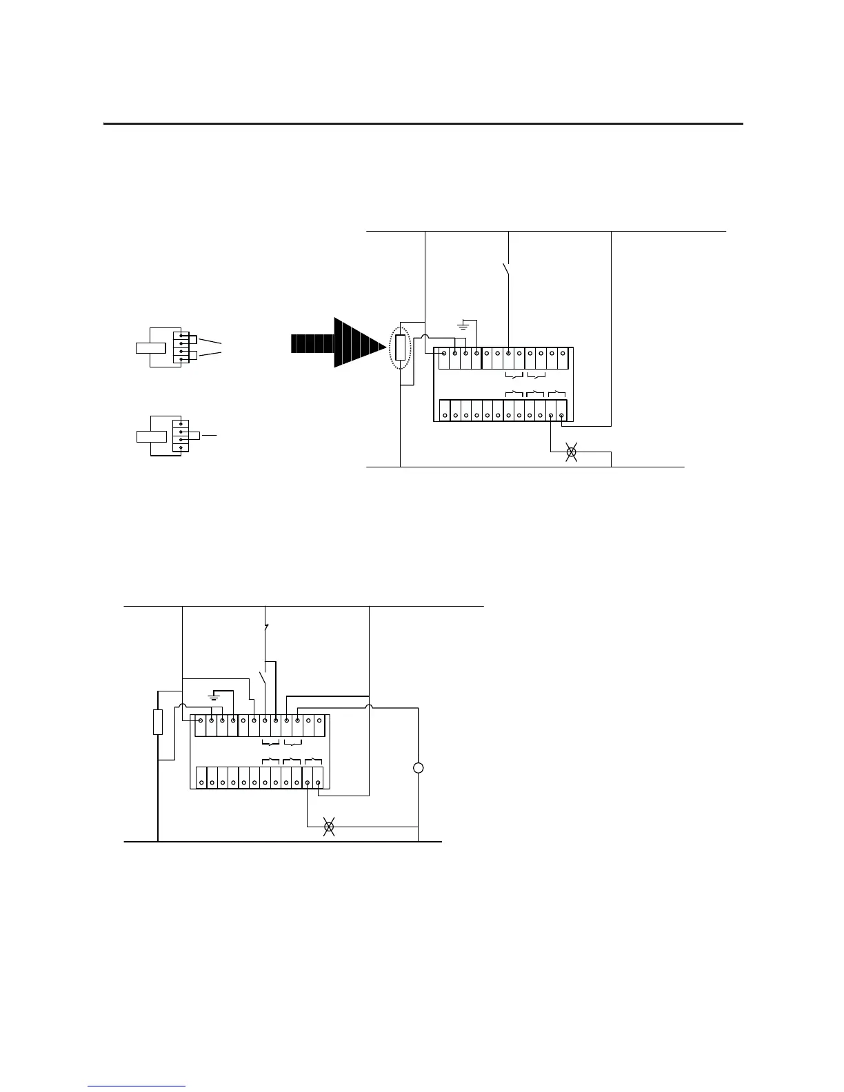
SMC Flex Control Terminals
Aux#1
Aux#4
27 28 29 30 31 32 33 34
Aux#3Aux#2
Hold In
11 12 13 14 15 16 17 18 19 20 21 22
23 24 25 26
SMC Flex Control Terminals
Aux#1
Aux#4
27 28 29 30 31 32 33 34
Aux#3Aux#2
Hold In
2 Wire
Device
Up-to-Speed
Indication
Fault
Indication
L1 (L+)
N (L-)
Programming Notes:
Aux#4 – Set for Fault
Parameter#132 – Set for Diable
Programming Notes:
Aux#1 – Set for Normal
Aux#4 – Set for Up to Speed
FAN
Start
L1 (L+)
N (L-)
FAN
K1
A1
A2
Stop
Connection Required
for DPI Control
Fig 1.x
3 Wire Control (With or Without DPI control), Isolation Contactor (K1),
and Up-to-Speed Indication
Fig 1.x
2 Wire Control (No DPI control or Option Stopping) with Fault Indication
Fan Power Terminations Example
(Separately Wired for F5...F480 Devices)
1
2
3
4
Factory Default Position
110/120 VAC
Optional Configuration
220/240 VAC
Jumpers
Supply
1
2
3
4
Supply
Jumper

 Loading...


