English-7
Input Power Conditions
I/O Terminal Block Specifications
Refer to the PowerFlex 40 User Manual for recommendations on
maximum power and control cable length.
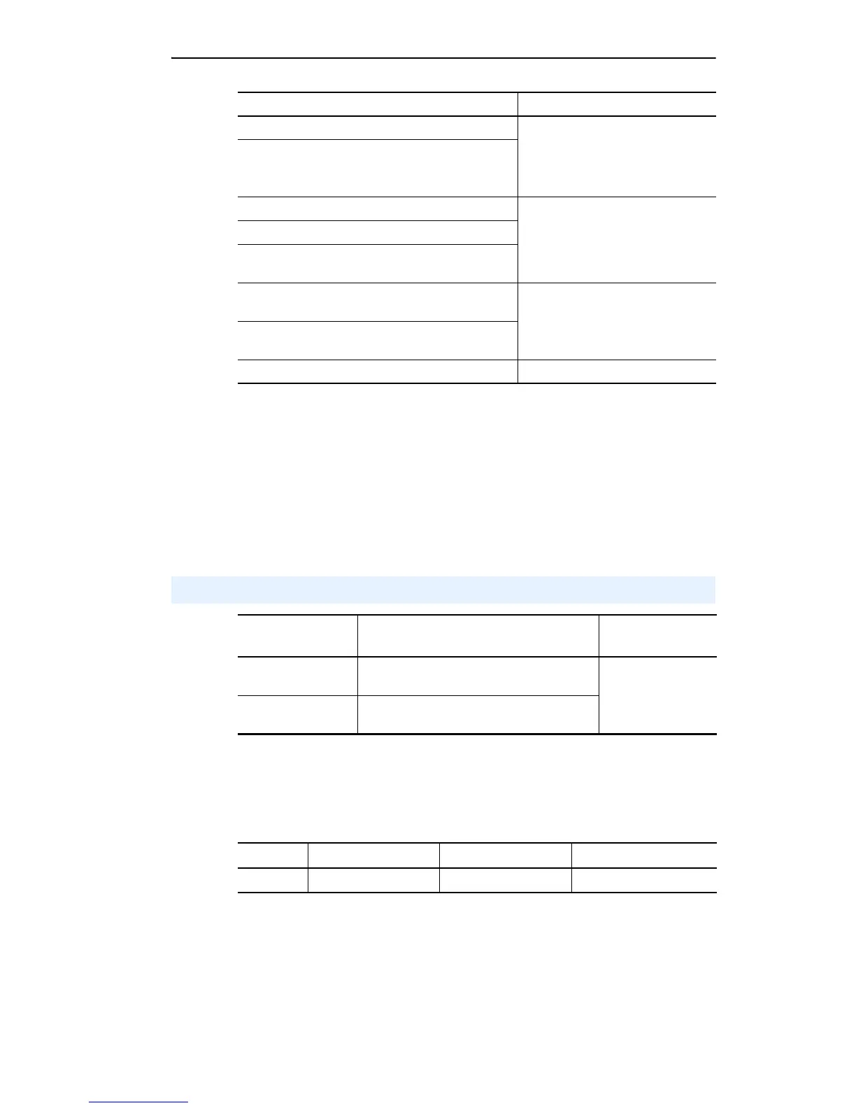
Input Power Condition Corrective Action
Low Line Impedance (less than 1% line reactance) • Install Line Reactor
(2)
• or Isolation Transformer
• or Bus Inductor – 5.5-11 kW
(7.5-15 HP) drives only
(2)
Refer to Appendix B of the PowerFlex 40 User Manual for accessory ordering
information.
Greater than 120 kVA supply transformer
Line has power factor correction capacitors • Install Line Reactor
• or Isolation Transformer
Line has frequent power interruptions
Line has intermittent noise spikes in excess of
6000V (lightning)
Phase to ground voltage exceeds 125% of normal
line to line voltage
• Remove MOV jumper to ground.
• or Install Isolation Transformer
with grounded secondary if
necessary.
Ungrounded distribution system
240V open delta configuration (stinger leg)
(1)
(1)
For drives applied on an open delta with a middle phase grounded neutral system, the
phase opposite the phase that is tapped in the middle to the neutral or earth is
referred to as the “stinger leg,” “high leg,” “red leg,” etc. This leg should be identified
throughout the system with red or orange tape on the wire at each connection point.
The stinger leg should be connected to the center Phase B on the reactor. Refer to the
PowerFlex 40 User Manual for specific line reactor part numbers.
• Install Line Reactor
I/O Wiring Recommendations
(3)
Wire Type(s)
(4)
Description Minimum Insulation
Rating
Belden 8760/9460
(or equiv.)
0.8 mm
2
(18AWG), twisted pair, 100% shield
with drain.
300V
60 degrees C
(140 degrees F)
Belden 8770
(or equiv.)
0.8 mm
2
(18AWG), 3 conductor, shielded for
remote pot only.
(3)
If the wires are short and contained within a cabinet which has no sensitive circuits,
the use of shielded wire may not be necessary, but is always recommended.
(4)
Stranded or solid wire.
Frame Maximum Wire Size
(5)
Minimum Wire Size
(5)
Torque
B & C 1.3 mm
2
(16 AWG) 0.2 mm
2
(24 AWG) 0.5-0.8 N-m (4.4-7 lb.-in.)
(5)
Maximum / minimum that the terminal block will accept - these are not
recommendations.