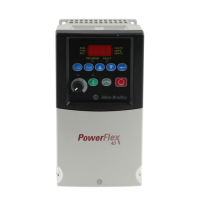
Do you have a question about the Rockwell PowerFlex 40 and is the answer not in the manual?
Warning about high voltage capacitors taking time to discharge after mains supply removal.
Warning about potential damage/injury from misapplied parameters A092/A094.
Warning that only qualified personnel should plan/implement installation and maintenance.
Warning about ESD sensitive parts and required static control precautions.
Warning that incorrect application or installation can cause damage or malfunction.
Specifies required clearances for proper drive cooling and air flow based on mounting options.
Lists acceptable ambient operating temperature ranges and corresponding enclosure ratings.
Shows the location of the jumper to be removed for disconnecting MOVs.
Details the procedure for removing the MOV jumper for phase to ground connections.
Details 12t overload protection for motor thermal management and class 10 protection.
Specifies hardware and instantaneous limits for overcurrent faults.
Lists trip voltages for overvoltage conditions across different input voltage ranges.
Lists trip voltages for undervoltage conditions across different input voltage ranges.
Specifies minimum and typical ride-through duration for control signals.
States the ride-through time for faultless power conditions.
Notes the inclusion of an internal brake IGBT and reference for DB resistor ordering.
Specifies acceptable wire types and ratings for power connections.
Lists recommended copper wire types for power connections.
Diagram and description of the terminal block for the B Frame.
Diagram and description of the terminal block for the C Frame.
Lists corrective actions for various input power conditions like low impedance or noise.
Specifies recommended wire types for I/O connections and their insulation ratings.
Illustrates the wiring connections for the control terminal block.
Lists and describes the function of each terminal in the control block.
Provides critical notes and important information regarding terminal connections and jumpers.
Details checks and confirmations required before powering the drive.
Instructions for applying AC power and control voltages to the drive.
How to adjust speed reference on IP66/4X drives via keypad or parameter.
Tips for setting the speed reference using internal frequency parameter A069.
Describes the different menu groups (Display, Basic Program, Advanced Program, Fault Designator).
Explains the meaning of each LED state on the integral keypad.
Details the function of each key on the integral keypad for navigation and control.
Detailed steps for navigating menus, selecting parameters, and changing values.
Parameters P031, P032, P033 related to motor nameplate voltage, frequency, and current.
Parameters P034, P035 for setting minimum and maximum output frequencies.
Parameter P036 for selecting the drive's start control method.
Parameters A051-A054 to configure functions for digital inputs.
Parameters A055 and A056 for configuring relay output selection and level.
Parameters A058, A059, A061, A062, A064 for configuring opto outputs.
Details faults related to auxiliary input, DC bus ripple, under/over voltage.
Covers faults for motor stall, overload, and heatsink over-temperature.
Explains faults for HW overcurrent, ground fault, and analog input loss.
Addresses faults related to phase shorts, parameter defaults, SW overcurrent, and I/O board failure.
Details faults for net loss, SVC autotune, comm loss, and power unit errors.
Details dimensions (mm/in) and weights (kg/lbs) for B and C frames.
Specific dimensional drawings for the IP20 NEMA/UL Type Open frames.
Dimensions for communication and RFI filter option kits for B and C frames.
| Brand | Rockwell |
|---|---|
| Model | PowerFlex 40 |
| Category | Controller |
| Language | English |