English-8
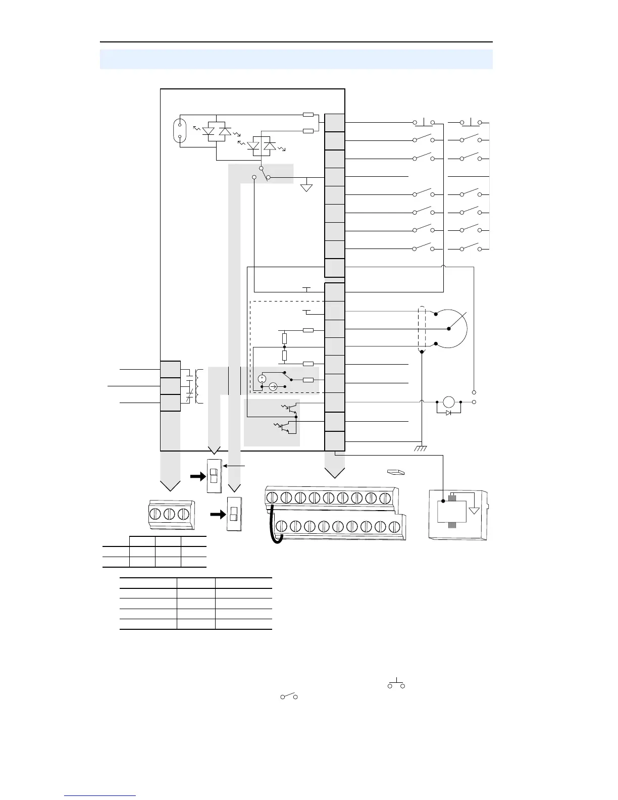
Control Wiring Block Diagram
(1)
Important: I/O Terminal 01 is always a coast to
stop input except when P036 [Start Source] is set to
“3-Wire” or “Momt FWD/REV” control. In three wire
control, I/O Terminal 01 is controlled by P037 [Stop
Mode]. All other stop sources are controlled by P037
[Stop Mode].
Important: The drive is shipped with a jumper installed between I/O Terminals 01 and 11. Remove
this jumper when using I/O Terminal 01 as a stop or enable input.
(2)
Two wire control shown. For three wire control use a momentary input on I/O Terminal 02 to
command a start. Use a maintained input for I/O Terminal 03 to change direction.
(3)
When using an opto output with an inductive load such as a relay, install a recovery diode parallel
to the relay as shown, to prevent damage to the output.
(4)
When the ENBL jumper is removed, I/O Terminal 01 will always act as a hardware enable, causing
a coast to stop without software interpretation. Refer to the PowerFlex 40 User Manual for more
information.
Control Terminal Block