Do you have a question about the Roger H30/643 and is the answer not in the manual?
Important steps before connecting to mains power supply.
Checks before connecting equipment and analysing risks.
Verify safety devices, thrust force, and indicate gate automation.
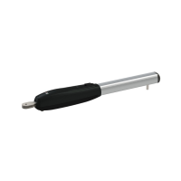
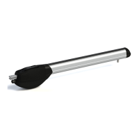
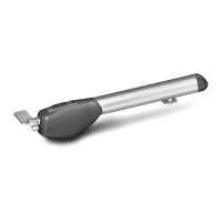
Details of different H30 models for sliding gates.
Voltage, frequency, and power consumption for models.
Force, operating speed, and temperature range of the automation.
Check gate structure, wheels, and manual movement smoothness.
Ensure guide shoes, ground rail, and gate stops are correctly installed.
Install anti-tilting system and check hinges.
Position plate correctly, bury in concrete, and ensure levelness.
Secure tie rods and respect distances for rack alignment.
Mount actuator on tie rods and align with the rack.
Tighten M10 nuts, check engagement, and re-install cover.
Set up for manual movement and slide gate to fix rack.
Ensure proper alignment, pitch, and 1-2mm clearance between pinion and rack.
Position mechanical tabs and magnetic brackets on the rack.
Find optimal stop position and avoid gate hitting stops.
Follow control unit instructions and connect motor wires.
Execute the mandatory earth connection for the actuator.
Connect FCA, FCC, and COM terminals for the magnetic limit switch.
Roger Technology details and compliance with EMC/Low Voltage Directives.
List of applied standards and CE mark information.
| Brand | Roger |
|---|---|
| Model | H30/643 |
| Category | Gate Opener |
| Language | English |