11
MESSA IN POSA DELLA PIASTRA DI FONDAZIONE • INSTALLATION OF THE FOUNDATION PLATE • POSE DE LA
PLAQUE DE FONDATION • VERLEGUNG DER GRUNDPLATTE • COLOCACIÓN DE LA LOSA DE CIMENTACIÓN
• INSTALAÇÃO DA CHAPA DE FUNDAÇÃO
MESSA IN POSA DELLA PIASTRA DI FONDAZIONE
Nella fase preliminare è indispensabile sapere quale tipo di cremagliera sarà installata per poter posizionare la piastra di fondazione in modo corretto. Come esempio si farà
riferimento ad una installazione tipo, con la piastra annegata nel calcestruzzo.
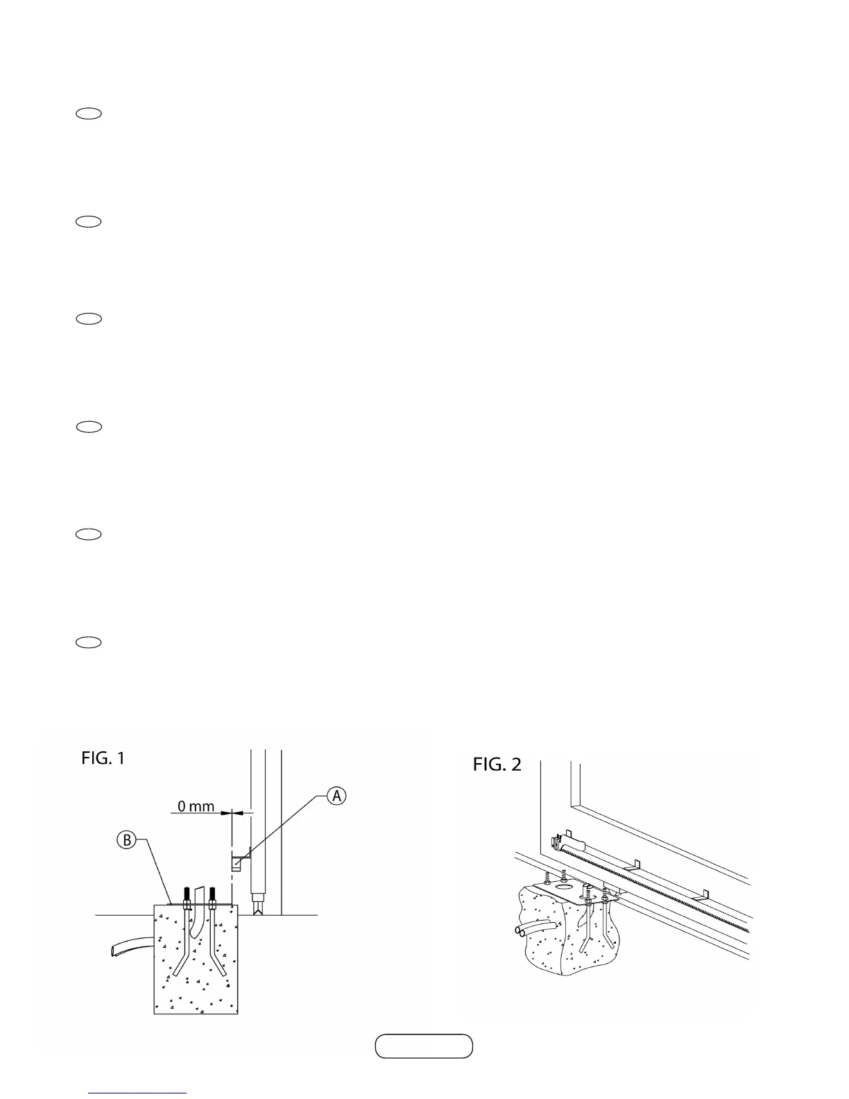
L’automazionepuòessereinstallataindifferentementeadestraoasinistra.Avvitare4dadida10MAnei4tirantiindotazione,pertuttoilletto,inlarlinei4foridellapiastra
di fondazione, bloccarli con altri 4 dadi – vedi g.1
Predisporrelapiazzoladicalcestruzzo,annegarelapiastradifondazionenelcalcestruzzo,perfettamenteinbollaeconlapartelettatadeitiranticompletamentein
supercie.E’importanterispettarelequotetralapiastradifondazione(B) e la cremagliera (A) come indicato in g.1.Faruscireitubiessibilidell’impiantoelettrico
preferibilmente nel foro di destra della piastra di fondazione (vista dall’interno) g. 2.
INSTALLATION OF THE FOUNDATION PLATE
In the preliminary stage it is indispensable to know the type of rack that will be installed in order to position the foundation plate correctly. A standard type of installation will be
taken as an example with the plate buried in concrete. The automation system may be installed on the right or left. Screw 4 nuts 10 MA into the 4 tie rods provided in the kit
forthewholelengthofthethreadandinsertthemintothe4holesofthefoundationplate;lockthemwithanother4nuts–seeg.1
Preparetheconcreteslab,burythefoundationplateintheconcrete,makingsureitislevelandthatthethreadedpartofthetierodsiscompletelyabovethesurface.Itis
important to respect the distances between the foundation plate (B) and the rack (A), as shown in g.1.Havetheexibleconduitsoftheelectricalsystemexitpreferablyfrom
the right-hand hole of the foundation plate (seen from inside) g. 2
VERLEGUNG DER GRUNDPLATTE
WährendderVorbereitungsphaseistesunerlässlichzuwissen,welcheArtvonZahnstangemontiertwird,umdieGrundplattekorrektpositionierenzukönnen.AlsBeispiel
wirdeinetypischeInstallationdargestellt,beiderdieGrundplatteinBetoneingelassenist.
DerAntriebkannsowohlrechtsalsauchlinksmontiertwerden.Die410MAMutternindie4mitgeliefertenZugstäbeganzeinschrauben,indie4BohrungenderGrundplatte
einsetzen und mit weiteren 4 Muttern festziehen - siehe Abb. 1.
DieBetonächevorbereitenunddieGrundplatteperfektnivelliertindenBetoneinbetten.DerGewindeteilderZugstäbemussganzherausstehen.Esistwichtig,dieMaße
zwischenderGrundplatte(B)undderZahnstange(A) einzuhalten, wie auf (Abb. 1)dargestellt.DieSchläuchederelektrischenAnlagevorzugsweiseausderrechten
BohrungderGrundplatte(voninnengesehen)herausführen(Abb. 2)..
POSE DE LA PLAQUE DE FONDATION
Dans la phase préliminaire, il est indispensable de savoir quel type de crémaillère sera installé pour pouvoir positionner correctement la plaque de fondation. L’exemple
donné se réfère à une installation type, avec la plaque noyée dans le béton.
L’automationpeutêtreinstalléeindifféremmentàdroiteouàgauche.Visser4écrousde10MAdansles4tirantsendotation,surlatotalitédulet.Lesenlerdansles4
trous de la plaque de fondation, les bloquer avec 4 autres écrous – voir g.1
Noyerlaplaquedefondationparfaitementd’aplombdanslebétonaveclapartieletéedestirantscomplètementensurface.Ilestimportantderespecterlescotesentrela
plaque de fondation (B) et la crémaillère (A) comme indiqué sur la g.1.Fairesortirlestuyauxexiblesdel’installationélectrique,depréférencedansletroudedroitedela
plaque de fondation (vue de l’intérieur) g. 2.
COLOCACIÓN DE LA LOSA DE CIMENTACIÓN
Enlafasepreliminar,esindispensablesaberquétipodecremalleraseinstalaráparapodercolocarlalosadecimentacióndemaneracorrecta.Comoejemplo,setomará
como referencia una instalación tipo, con la losa sumergida en el hormigón.
El automatismo puede instalarse indiferentemente a la derecha o a la izquierda. Atornille 4 tuercas de 10 MA en los 4 tirantes asignados en el equipamiento base (una tuerca
porcadatirante),portodalarosca;introduzcaéstosenlos4agujerosdelalosadecimentaciónybloquéelosconotras4tuercas–véaselag. 1.
Predispongalaplataformadehormigónysumerjalalosadecimentaciónenelhormigón,perfectamenteniveladayconlaparteroscadadelostirantescompletamenteen
supercie.Esimportanterespetarlasmedidasentrelalosadecimentación (B) y la cremallera (A), como se indica en la g. 1.Hagasalirlostubosexiblesdelainstalación
eléctricapreferiblementeporelagujeroderechodelalosadecimentación(vistadesdedentro)g. 2.
INSTALAÇÃO DA CHAPA DE FUNDAÇÃO
Nafasepreliminar,éindispensávelsaberqualtipodecremalheiraseráinstaladaparapoderposicionarachapadefundaçãodemodocorrecto.Comoexemplo,toma-se
comoreferênciaumainstalaçãotipo,comachapaembebidanobetão.Aautomaçãopodeserinstaladaindiferentementeàdireitaouàesquerda.Fixe4porcasde10MA
nos4tirantesfornecidos,emtodaahaste,introduzi-losnos4orifíciosdachapadefundação,bloqueie-oscomoutros4porcas–veja g. 1.Prepareabasedebetão,
coloque a chapa de fundação embebida no betão, perfeitamente nivelada e com a parte roscada dos tirantes completamente na superfície. É importante respeitar as
quotas entre a chapa de fundação (B) e a cremalheira (A) conforme ilustra a g. 1.Passeostubosexíveisdosistemaeléctricodepreferênciapelofuroposicionadoà
direita da chapa de fundação (vista pela parte interior) g. 2.
Serie H30
GB
I
D
F
P
E
 Loading...