Instrument tour
R&S
®
FPC
18Getting Started 1328.7409.02 ─ 05
The frequency range of the RF input is specified in the datasheet.
The attenuation range is between 0 dB and 40 dB.
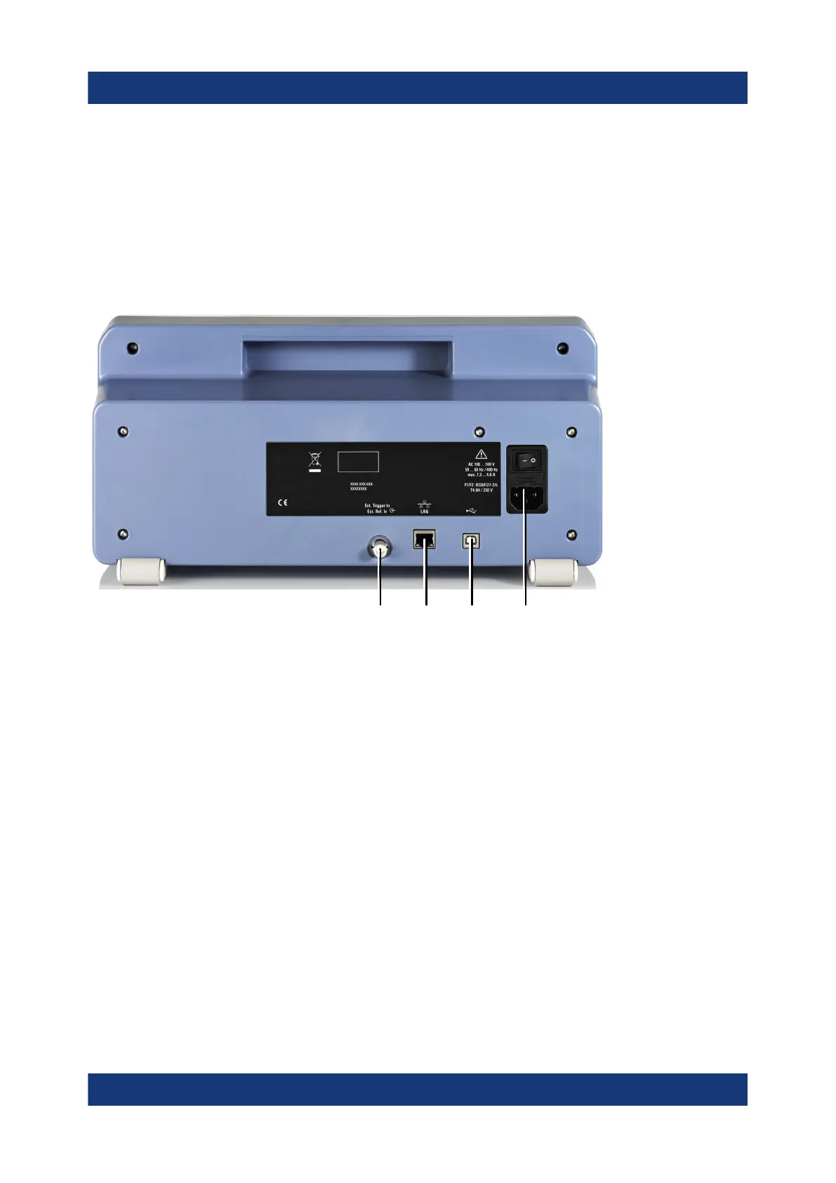
4.2 Rear panel
1 432
Figure 4-2: Rear panel of the R&S
FPC
1 =
Trigger input / external reference
2 = LAN
3 = USB port (type B)
4 = Power supply
Power supply
The AC power supply and main power switch are located in a unit on the rear
panel of the instrument.
The main power switch has the following states.
●
Position "1": The instrument is supplied with power.
●
Position "0": The instrument is disconnected from the power supply.
Trigger input / external reference
This female BNC connector allows you to connect an external trigger signal or an
external reference signal.
Rear panel
 Loading...


