Operating concepts
R&S
®
NRP Series
42Getting Started 1419.0170.02 ─ 18
5.7 R&S NRX
In a measurement, the R&S NRX uses all power sensor-dependent measurement
functions and displays the results. Thus, you can configure both the measure-
ment and the power sensor.
Required equipment
●
R&S NRP power sensor
●
R&S NRP‑ZK8 cable to connect the power sensor to the R&S NRX
●
R&S NRX
Setup
NRP
3-Path Diode Power Sensor
MHz to GHz, 100 pW to 200 mW (−70 dBm to +23 dBm)
SMART SENSOR TECHNOLOGY
1
2
3
4
6
5
Figure 5-4: Setup with an R&S
NRX base unit
1 = Signal source
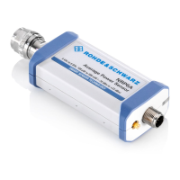
2 = R&S NRP power sensor
3 = Host interface connector
4 = R&S NRP‑ZK8 cable
5 = Sensor input connector of the R&S NRX
6 = R&S NRX base unit
1. NOTICE! Incorrectly connecting or disconnecting the power sensor can dam-
age the power sensor or lead to erroneous results. Ensure that you connect or
disconnect the power sensor as described in Chapter 3.4, "Connecting to a
DUT", on page 13.
Connect the power sensor to the signal source.
2. Connect the cables as shown in Figure 5-4.
If the power sensor is a R&S NRP LAN power sensor, you can set up a LAN
connection instead of using the sensor input connector of the R&S NRX. See
Chapter 3.7.3, "Using a LAN connection", on page 20.
R&S NRX
 Loading...