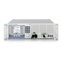
Digital Reprogrammable Software Radios R&S M3SR 8
Built-in interfaces
Serial interfaces 2 serial interfaces up to 115 kbit/s; one
RS-232-C, the other one can be config-
ured as RS-232-C/RS-422/RS-485,
parameters adjustable for radio con-
trol, configuration, user data (SECOS
mode with DPP)
LAN 2 interfaces acc. to Ethernet IEEE802.3,
RJ-45 connectors, 10baseT;
for radio control, configuration and
software download
RF power amplifier (PA) and RF filter
control interfaces
2 user-configurable interfaces for
Rohde&Schwarz PA and filters: 2 x PA
or 2 x filter or 1 x filter + 1 x PA; others
on request
RF connectors for antennas N female for TX or common TX/RX
antenna and BNC female for RX
AF standard interfaces 2 narrowband, 2 wideband;
for voice and user data
External reference frequency for special applications; input/output
(BNC connector): 0.8/1/2/5 or 10 MHz
configurable, can be daisy-chained
Timing system input/output to receive/transmit TOD
(time of day) from/to external timing
system (e.g. R&S GT400) acc. to
STANAG 4246, STANAG 4430,
ICD-GPS-060
Key distribution device interface
(fill gun)
KYK-13, KOI-18, DTD (data transfer
device) conforming to DS100/DS101/
DS102; Rohde&Schwarz KDD (key
distribution device); external mainte-
nance tool
External crypto devices KY 58, KY 57 (others on request)
Miscellaneous interfaces e.g. PTT, carrier SQ, NOGO, INHIBIT,
switched DC for external devices; other
I/Os on request
Headphones output max. 1 V at 150 : (adjustable to lower
values down to 0 V), NF7-type headset
connector
Integrated loudspeaker
max. 0.4 W, volume adjustable via knob
Microphone inputs dynamic micro: 0 mV to 25 mV into
150 :
amplifier micro: 0 V to 1 V/150 :,
15 mA to 20 mA, 9 V DC max.,
NF7-type headset connector
General data
Operating temperature range –20qC to +55qC
Storage temperature range –40qC to +70qC
Humidity d95% at +55qC to MIL-STD-810F
method 507.2 and DIN EN 60068-2-30,
+25qC /+55qC
Dust and water protection
Control unit
Radio
IP 54
IP 20, upgradeable to IP 32, for radio
front only
Fungus protected to MIL-STD-810C method
508.2
Permissible altitude
Permanent operation
5 min operation
Transport
5000 m asl
10000 m asl
10000 m asl
Vibration 5 Hz to 55 Hz, 0.4 mm double
amplitude, test period: 30 min to DIN
EN 60068-2-6, MIL-STD-167-1 type 1,
STANAG4138
Shock
45 Hz to 2000 Hz,
d
40 g, 3 shocks in two
of three axes to DIN EN 60068-2-27,
MIL-STD-810D method 516.3
EMI/EMC EN301489
MIL-STD-461E: CE101, CE102, CE106,
CS101, CS114, RE102, RS101 (maxi-
mally achieved test field strength
160 dBpT), RS-103 (2 MHz to 1 GHz,
test field strength 10 V/m)
Transients and spikes (AC supply) STANAG1008 edition 8 and
MIL-STD-1399 sec.103 type 1
Electrical safety Directive 72/23/EEC (CE mark), IEC 950,
VDE0804, VDE0805, VDE0866,
EN60950
Cooling sensor-controlled forced-air cooling by
integrated fans, air flow direction from
front to rear side; if there is a front
door, it should have sufficient air inlets
Power supply
DC operation
AC operation
Receiver
Transmitter, transceiver
AC/DC operation
Power consumption
(example: VHF/UHF transceiver with
CCP, EPM, guard RX)
28 V nominal, 19 V to 31 V with some
degradations (acc. to Directives
89/336/EEC and 72/23/EEC)
90 V to 264 V, 47 Hz to 63 Hz
90 V to 264 V, 47 Hz to 63 Hz;
110 V at 400 Hz to 440 Hz (with external
R&S IN4000A)
automatic switchover; priority to AC
depending on configuration and
DC/AC supply
approx. 80 W (receive mode, DC)
approx. 380 W/505 VA for VHF/UHF
30 W AM/100 W FM (transmit mode,
AC/DC)
Dimensions
Transceiver/transmitter (DC) 19" plug-in, 3 HU
Transceiver/transmitter set (AC/DC) 19" plug-in, 3 HU + 1 HU
(AC power supply)
Receiver/multiple receiver (AC/DC) 19" plug-in, 3 HU
Additional space for rear cabling 200 mm recommended
Weight
Receiver approx. 14 kg
Transceiver approx. 16.5 kg
EPM transceiver incl. guard receiver approx.17.5 kg
External Universal Power Supply
R&S IN4000A
5.7 kg
Logistics
MTTR on module level 15 min typ.
Important note: All adjustments, settings and configurations stated above can
be performed locally or remotely via software.

 Loading...