Do you have a question about the Rohde & Schwarz M3SR Series 4100 and is the answer not in the manual?
| Modulation Types | AM |
|---|---|
| Sensitivity | 0.25 μV for 12 dB SINAD |
| Interfaces | RS-232, USB, Ethernet |
| Channel Spacing | 25 kHz |
| Operating Modes | Simplex, Half-duplex |
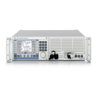
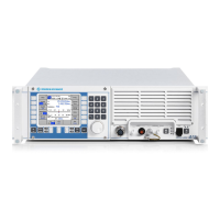
Overview of the R&S M3SR Series 4100 HF Transceiver and its functionalities.
Details the physical design, modularity, and internal components of the transceiver.
Explains the operational capabilities and working principles of the transceiver.
Covers frequency ranges, output power, and general operating parameters.
Details supported voice transmission modes and signal modulations.
Explains data transmission capabilities and supported data rates.
Lists the necessary test equipment and tools for functional testing.
Describes the procedure and expected results for built-in tests.
Outlines the tests required to verify performance specifications.
Basic troubleshooting steps involving visual checks of connections and cables.
Guides on resolving issues identified by built-in tests.
Diagnosing and resolving failures identified during specification tests.
Interpreting LED status indicators for diagnostics on the synthesizer module.
Procedures for safely opening the transceiver and preparing for module removal.
Steps for reassembling the transceiver after module replacement.
Instructions for removing and installing the Digital Selector module.
Information on factory settings and customer-specific configurations.
Details on software delivery packages and update procedures.
Explanation of option key loading and distribution for radio controllers.
List of component numbers and identifiers for spare parts.
References to interface descriptions, circuit diagrams, and parts lists.