065 75$16&(,9(5 ; $ ; $
Operator’s Manual • User Information
– 1.6 – 6076.0822.12.01
)XQFWLRQLQJHJ;7 $0RG
(See Fig. 1.4)
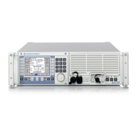
The Radio Platform contains the central processor (= server) of the M3SR Transceiver. Via
LAN/Ethernet, the server is connected to its clients. Clients may be an integrated Control Unit
GB 4000C (mod. 02) and/or further Control Units GB 4000C (mod. 03) connected via the LAN
connector X20 and a LAN hub, or customer-specific devices. The clients plus the software
package DS4400A form the MMI (= man-machine interface) of the M3SR Transceiver. Clients
are controlled by using the GB2PP protocol. The MMI guides the operator through menu-based
operating procedures and selectively visualizes all states on the display. Commands are en-
tered by making use of the control elements and the keypad. Operation and indication of the
transceiver’s operating status are both menu-oriented, operator interaction is performed via the
display and keyboard. The modules are controlled by the central processor via the Radio Mod-
ule Bus (RMB). The Radio Platform stores all parameters relating to the individual modules. A
system monitor monitors the temperatures and operating voltages. In a clock section all clock
signals needed by the radio platform are generated. The RMB connects the modules of
XT 4410A to one another and also to the central processor and the I/O interfaces. Serial inter-
faces are used for data transmission and remote control purposes. Parallel interfaces serve as
discrete inputs and outputs and control for instance an externally connected filter and / or am-
plifier. An Audio Frequency Interface (AFI) processes the analog signals in digital form so that
they can be transmitted digitally on the Radio Data Bus (RDB).
The Front Panel connected at the Radio Platform carries the control and display elements for
handling the basic transceiver functions. An Ethernet port is available for sending and receiving
data for service purposes (configuration and software download).
When the transceiver operates in receive mode, the RF signal is taken from antenna connector
X30 to the VHF/UHF Transmitter Board. From here it is routed via a Tx/Rx switch to the UHF
Filter FD 4430. The input stages of the filter are directly protected for electrostatic discharge.
The filter is working for the VHF/UHF Receiver ET 4400 (main receiver) as a preselector to re-
duce the interfering levels from other radios of the platform. In the main receiver, the RF signal
passes along a VHF path (100 to 224.975 MHz) or a UHF path (225 to 512 MHz) to the mixer
stages. The mixer stages get the LO signal (365 to 652 MHz) from VHF/UHF Synthesizer
GF 4400T. The AGC-controlled 2
nd
IF signal with a frequency of 455 kHz is demodulated in the
digital section of the receiver. The demodulated baseband signal is taken to the RDB for further
processing.
In transmit operation, VHF/UHF Synthesizer GF 4400T generates a carrier frequency in the
range from 100 MHz to 512 MHz. For amplitude modulation, this carrier frequency is modu-
lated by the VHF/UHF Transmitter Board. FM signals (both analog FM and digital FSK signals)
are generated by the synthesizer to be merely amplified by the VHF/UHF Transmitter Board
(signal RF_Drive). After amplification and filtering, the resulting signal is made available at an-
tenna connector X30. The UHF Filter FD 4430 is working as postselector. The filter chain is
located within the transmit path of the radio. The selectivity of the filter chain reduces the trans-
mitted noise energy of the radio which may degrade the sensitivity of other receiving radios on
the platform.
Interface Module GH 4450 connects the RMB and discrete signals between the Radio Plat-
form, the VHF/UHF Transmitter Board and up to three further rear modules. Switchover be-
tween transmission and reception is effected via the RMB.
The integrated DC Power Supply uses the +28-VDC input voltage to generate all voltages re-
quired in XT 4410A.

 Loading...