Ceramics: 06/2004
23
Appendix F:
Electrical
connection
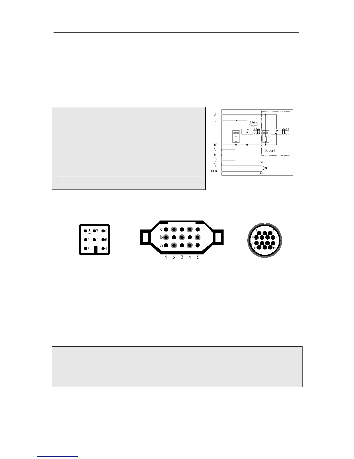
Simplified switch diagram of a kiln
Important Note:
The specifications given here are exemplary only. The
electrical connections are determined by the customer and
often deviate from the specifications given in this example.
Please check the documentation provided by the kiln
manufacturer. If the controller layout is suitable for more than
one zone or if it is equipped with more than two outlets,
please use the HAN15DX connection (see additional
description).
Plug designation
HAN7D a
HAN15D a CPC14 a
Connection Function HAN7D a HAN15D a CPC14a
a Additional control outlet 7 C3 12
b Control outlet connector (phase) 6 A3 14
c Control outlet connector (zero) 1 B3 13
d Ground wire *
termination fitting
11
e Power supply phase 5 A1 8
f Power supply zero 2 B1 9
g Thermocouple + 3 B5 1
h Thermocouple – (Pt Rh Pt) 4 C5 2
n Thermocouple - (NiCrNi) 4 A5 3
* The ground wire must be connected!
Important Note:
Please compare the type of the thermocouple with the type specification that is stated on the back of
the controller. Otherwise you might cause damage to the kiln and the kiln content!
We reserve the right to make changes contributing to technical improvement.
Instruction Manual TC 504 V1.20 (C) 2004 HELMUT ROHDE GMBH DEUTSCHLAND
Ground wire
220 V phase
2
20 V zero
Thermocouple


 To Previous Page