The terminal can be easily installed using our dedicated
floor stand or it may be placed on a counter
unit can also be mounted securely to a wall using the
optional wall bracket from Boscop.
Power down and unplug the copier
Remove the back and/or side panels to reach the
copier’s foreign interface connector
Attach the copier harness between t
(DB15) and the copier’s foreign interface connector.
If applicable (not all machines require this), switch the
copier to foreign device mode (key counter, card
reader, coin op etc.) The copier service technician has
Check that all connections are secure, then plug in and
The copier should be disabled until a valid user ID is
entered and authorized via the terminal.
Replace the copier panel(s).
erminal has been thoroughly tested prior to
shipping and so it is unlikely any parts will fail on
or the external interfacing. Once
you have checked the connec
network link light on, it is situated
beneath the up/down arrows
installation of network software. Check with your
software provider’s support staff or help des
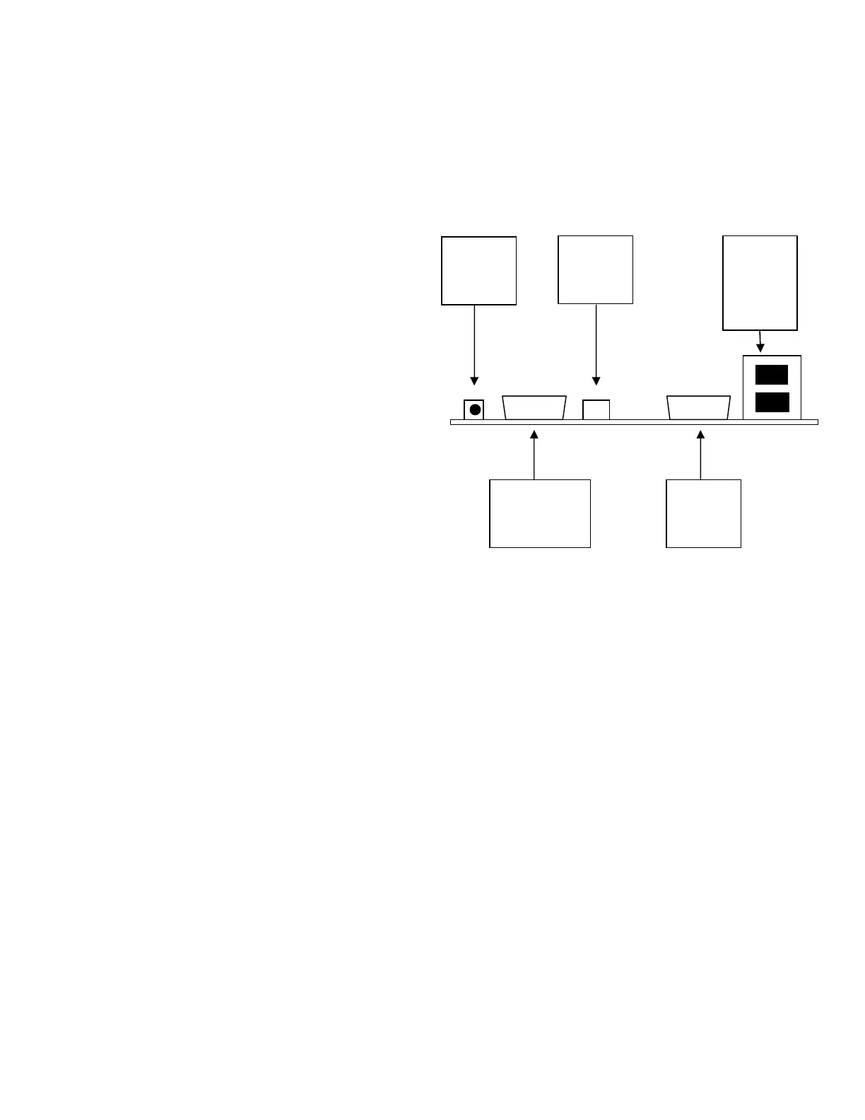
Power cord to wall socket (90 VAC to 264 VAC)
Ethernet cable (not supplied)
Copier interface (harness)
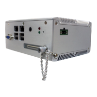
All the connection points are on the rear of the
nal. Be sure that the copier interfac
connected BEFORE powering up the
copier; connecting the copier while power is on may
severely damage the copier and the
Once the network cable is connected and power is
. If it does not, then check the
network connections and cabling.
It does not matter which of the network ports is used
for the incoming or outgoing network connecti
VCC network switch operates identically in either of the
DB9 serial port connections
Should you intend to connect an external reader to the
VCC it is important to know the pin
Rts (flow control only, not active)
In most cases you will only need to use pins 3, 5 and either 6
or 9. It is important that the external reader issues both
start character (STX) and an end character (ETX) so that the
VCC can transmit the package to the server. If in any doubt
about this, contact Boscop for technical assistance.