20
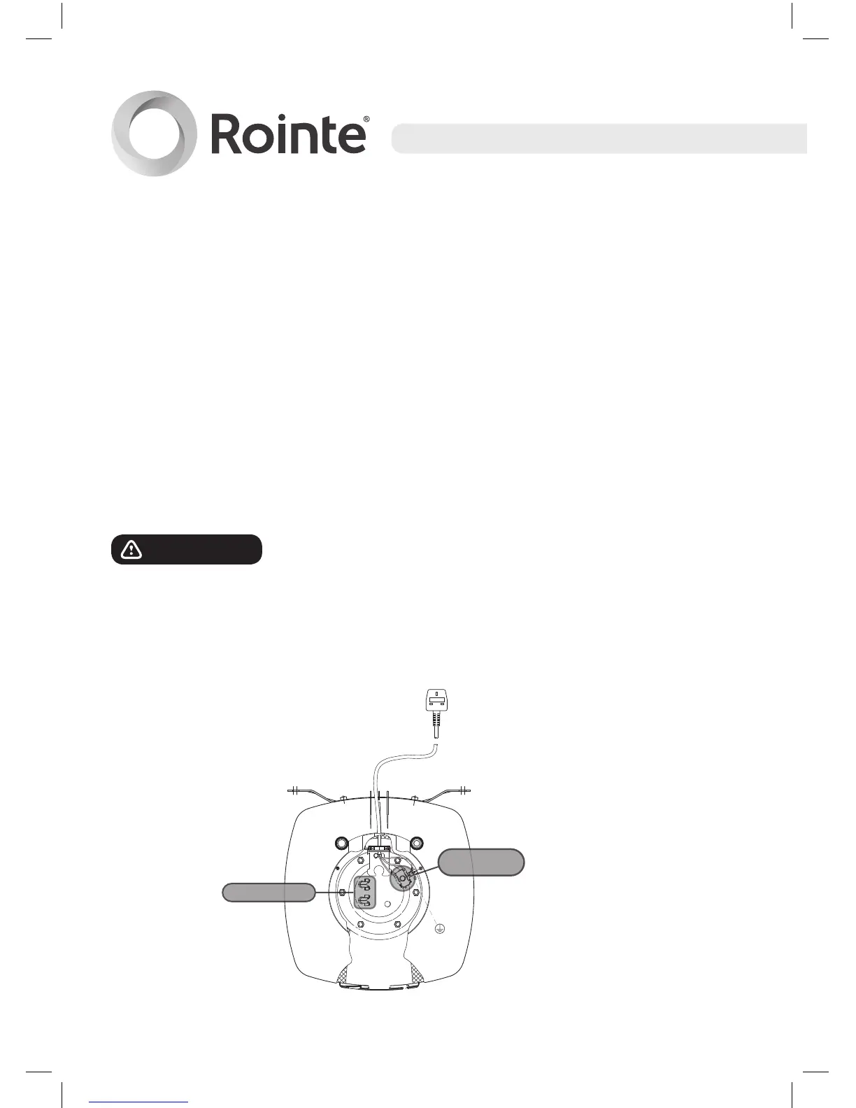
5.2. Wiring diagram
a) The power supply to the heater must be via a double pole isolator
switch or controller, having contact separation of at least 3 mm,
to comply with BS 6141 and must be fully earthed. In case of an
electric problem, check that the wiring follows the diagram below:
i. The Earth wire is connected to the terminal on the cylinder
marked with the earth symbol.
ii. The Live wire is connected to the high temperature cut-out
terminal.
iii. The Neutral wire is connected to the high temperature cut-out
terminal.
WARNING!
DO NOT SWITCH ON THE ELECTRICITY
SUPPLY UNTIL INSTRUCTED TO DO SO IN THE COMMISSIONING
PROCEDURE AND ONCE THE UNIT IS FULL OF WATER.
Wiring diagram - D Series water heater.
COLD
HOT
EARTH
CONNECTION
HEATING ELEMENTS
THERMAL
CUT OUT