17
Mar. 2008 GT-10
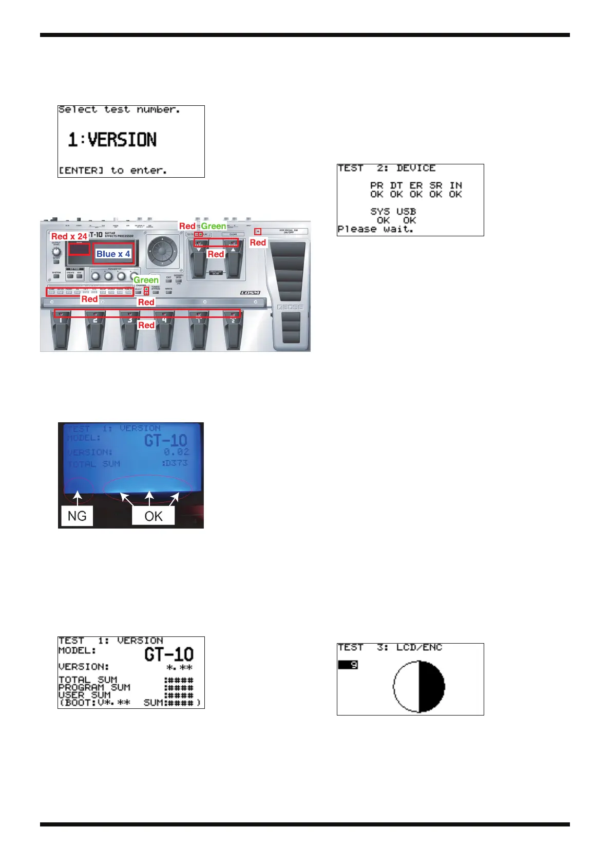
0. Starting the Test Mode
1. Hold down [OUTPUT SELECT] and [SYSTEM] and switch on the power.
* Continue holding down these buttons until a screen like the one shown below
appears.
fig.1version.eps
2. Verify that all LEDs light up.
3. Verify that the color of the LEDs is correct.
fig.ledall-GT-10.eps
4. Apply impact and verify that the LEDs and LCD screen do not go dark or
disappear.
5. Verify that all 4 backlight LEDs at the bottom of the LCD screen light up.
Example of defective illumination of the LEDs for the LCD-screen
backlight
fig.lcd-bl-led.eps
1. VERSION
Version Verification
1. Display 1: VERSION on the screen.
2. Press [CATEGORY/ENTER].
The version number (*.** in the figure) and the checksum values (#### in
the figure) appear on the screen.
fig.version-GT10.eps
TOTAL SUM: The total of the following three items
PROGRAM SUM: The unit’s main program
USER SUM: User data
BOOT: The boot program
Unless instructed otherwise, for the checksum, verify the PROGRAM
SUM value.
3. Press [EXIT].
4. Press [CATEGORY/ENTER] to go back to the test-item selection screen.
2. DEVICE
Testing of the Peripheral ICs for the CPU and for
the DSP
1. Use the dial to choose 2: DEVICE.
2. Press [CATEGORY/ENTER] to display the screen shown below.
fig.2device2.eps
If OK is displayed for all items, execution automatically advances to the
next test.
Descriptions of Errors
PR Check of DSP (IC3) internal program RAM
An error indicates either an internal defect in the DSP (IC3) or a
defective bus connection with the CPU (IC2).
DT Check of DSP (IC3) internal data RAM
An error indicates either an internal defect in the DSP (IC3) or a
defective bus connection with the CPU (IC2).
ER Check of the SDRAM (19) connected to the DSP (IC3)
An error indicates either an internal defect in the SDRAM or a
defective connection between the DSP (IC3) and the SDRAM
(19).
SR Check of the DSP (13) internal sampling-rate converter
An error indicates either an internal defect in the DSP (IC3) or a
defective bus connection with the CPU (IC2).
IN Check of DSP (13) -> CPU (IC2) interrupt operation
An error indicates a defective interrupt connection (IC3 pin 101)
from the DSP (13) to the CPU (IC2).
SYS Check of the user data EEPROM (IC37)
An error indicates either a defect in IC37 or a defective
connection between IC37 and the CPU (IC2).
USB Check of the USB TUSB (IC11) and USB boot data EEPROM
(IC13)
An error indicates either a defect in the TUSB (IC11) or EEPROM
(IC13), or a defective connection between the TUSB (IC11),
EEPROM (IC13), and CPU (IC2).
3. LCD/ENC
Testing Covering LCD Contrast, Missing LCD Dots,
and Encoder Operation
1. Use the dial to choose 3: LCD/ENC.
2. Press [CATEGORY/ENTER] to display the screen shown below.
fig.3lcdenc2.eps
3. Verify that turning the dial counterclockwise makes the contrast
progressively fainter.
4. Verify that turning the dial clockwise makes the contrast progressively
deeper.
 Loading...