9
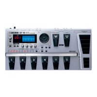
Mar. 2008 GT-10
Screw
Important Notes When Disassembling
Guard Against Lost Parts
When disassembling, first check and verify the disassembly procedures, then
carry out actual disassembly operations. Be especially careful to ensure that
the following parts are not lost.
• Jack Bushing (#G2257327R0)
• Insulating Washer 14.5X9.2 (#G2637118R0)
• USB Connector Cap (USBC-1) (#05015034)
Components Mounted on the SW VR
Board
When replacing the LED spacer (#G2147913R0) or keytop unit (#G2497020R0)
on the SW VR Board, first detach LED1 or LED2 and LED3 shown in the
Exploded View (p. 6), then carry out the replacement.
* When mounting the LEDs, be careful to orient the parts correctly.
Modifying the Wiring
The length of the following ribbon cables differs depending on the production
period. If the length is too long, modify the cable as shown below.
• 3-pin ribbon cable between SW VR Board CN105 and ENC (encoder)
Board CN501 (A in the figure below)
• 9-pin ribbon cable between Pedal Board CN202 and Bank Board CN301
(B in the figure below)
fig.wiring-set1.eps
Tape Application
After installing the SW VR Board, use Filament Tape #898 (#40122645) to
secure the 2-pin wiring from the LCD unit to the Insulating Sheet
(#G2257331R0) as shown in the figure below.
fig.tape.eps
No. Part Code Part Name Description Q’ty
a H5049003R0 SCREW M4X4 NI 5
b H5049004R0 SCREW M3X10.5 NI 5
c 40563989 SCREW 4X8 TAPTITE S BINDING NI 1
d 40019123 SCREW 3X8 BINDING TAPTITE S BZC 7
e 40011278 SCREW 3X8 BINDING TAPTITE P FE ZC 28
f 40017934 SCREW M3X6 PAN MACHINE W/SW+PW(L) FE ZC 8
g 40342712 SCREW M3X6 PAN MACHINE W/SW+SMALL PW BZC 12
j 40011312 SCREW 3X8 BINDING TAPTITE P BZC 3
r H5039521R0 NUT M7 5
s H5039510R0 NUT M9X12X2T NI 7
t H5039158R0 WASHER M9X14X0.5T NI 6
u H5039520R0 NUT M9 2
v H5039126 M9 WASHER 2
 Loading...