EasyManua.ls Logo

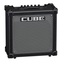
Roland CUBE-60D User Manual

Roland CUBE-60D
24 pages
To Next Page IconTo Next Page
Page #1 background imageLoading...
Page #1 background image
Issued by RJA
Copyright © 2004 ROLAND CORPORATION
All rights reserved. No part of this publication may be reproduced in any form without the written permission
of ROLAND CORPORATION.
Printed in Japan (0500) (TP)17058254E0
JULY.2004
CUBE-60D
CAUTIONARY NOTES ...................................................2
SPECIFICATIONS.............................................................2
LOCATION OF CONTROLS ..........................................4
LOCATION OF CONTROLS PARTS LIST .................. 5
EXPLODED VIEW(CABINET)........................................6
EXPLODED VIEW(CHASSIS).........................................8
PARTS LIST......................................................................10
CHECKING THE VERSION NUMBER.......................14
TEST MODE.....................................................................14
NOTE WHEN EXCHANGING AC CORD.................16
BLOCK DIAGRAM/WIRING DIAGRAM ................ 18
CIRCUIT BOARD(MAIN BOARD DIGITAL) ........... 20
CIRCUIT DIAGRAM(PANEL BOARD)..................... 22
CIRCUIT DIAGRAM(MAIN BOARD DIGITAL
PANEL BOARD ) ........................................................... 24
CIRCUIT DIAGRAM(MAIN BOARD ANALOG) .... 26
CIRCUIT DIAGRAM(MAIN BOARD POWER
SUPPLY) .......................................................................... 28
Question and Answer IconNeed help?

Do you have a question about the Roland CUBE-60D and is the answer not in the manual?

Roland CUBE-60D Specifications

General IconGeneral
BrandRoland
ModelCUBE-60D
CategoryMusical Instrument Amplifier
LanguageEnglish

Summary

SPECIFICATIONS

Electrical and Physical Specifications

Details the amplifier's power, input, speaker, controls, connectors, dimensions, and weight.

TEST MODE OPERATIONS

Test Mode Setup and Operation

Instructions on entering, exiting, skipping tests, and overview of test items.

Volume Test Procedure

Procedure to test the volume knob functionality and DSP response.

Switch Test Procedure

Procedure to test the functionality of various switches on the unit.

BLOCK DIAGRAM AND WIRING DIAGRAM

System Block Diagram

High-level functional block diagram of the amplifier.

Internal Wiring Diagram

Detailed wiring diagram illustrating internal connections.

CIRCUIT DIAGRAM(PANEL BOARD)

Panel Board Schematic

Schematic diagram of the panel board's circuitry.

CIRCUIT DIAGRAM(MAIN BOARD DIGITAL)

Main Board Digital Circuit Schematic

Schematic diagram of the digital section of the main board.

CIRCUIT DIAGRAM(MAIN BOARD ANALOG)

Main Board Analog Circuit Schematic

Schematic diagram of the analog section of the main board.
CIRCUIT DIAGRAM(MAIN BOARD POWER SUPPLY)

Related product manuals