24
Apr. 2014 CUBE-STEX
DSP/EEPROM Test
When the unit enters the Test Mode, DSP and EEPROM Test starts automatically.
The three LEDs at the center of the panel light up in the sequence of LEFT → CENTER → RIGHT to indicate the progress of the testing, then go dark in this
sequence of LEFT → CENTER → RIGHT.
If the test result is OK, testing is completed in a very brief time, and the LEDs are automatically initialized for the following Switch and LED Test (p. 24).
If the test result is NG (not OK), one of the LEDs shown in the table below lights up to indicate the corresponding device where the problem occurred.
* If the test result is NG (not OK), execution cannot advance to the next test item.
Switch and LED Test
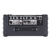
Carry out operations in the sequence shown in the table below and verify the status of the corresponding LEDs.
* If an error is made in the order of operations, or of a test is failed, execution cannot advance to the next operation.
* When operating the OUTPUT POWER switch, make a definite stop at each position. If the switch is moved too rapidly, without sufficient stopping, its operation might be
ignored.
In this case, return the switch to its original position and redo the operation.
o: lights, *: flashes, -: goes off
Pulling out the plug from AUDIO IN makes execution advance automatically to the next test item.
LED Faulty Device
LEFT IRAM
CENTER PRAM
RIGHT ERAM
BATTERY LOW EEPROM
LED
Operation TUNER LEFT CENTER RIGHT CHECK
/MUTE
FULL HALF LOW
Initial state o * o o o o o o
Slide the switch, press/release the buttons.
1 Set INPUT SELECT to INST. * - o o o o o o
2 Press TUNER. * - - o o o o o
3 Press TUNER again. - - - - * o o o
4 Press and hold CHECK/MUTE. - - - - o o o o
5 Release CHECK/MUTE. - - - - - * o o
6 Set OUTPUT POWER to NORMAL. - - - - - - * o
7 Set OUTPUT POWER to MAX. - - - - - - - *
8 Set LINE OUT MODE to STEREO LINK. o o o o * o o o
Insert a 1/4-inch phone plug/pull out, depress a pedal.
9 Insert into PHONES. o o o o o o o o
10 Pull out from PHONES. o o o o - * o o
11 Insert into AUX IN. o o o o - o o o
12 Pull out from AUX IN. o o o o - - * o
13 Insert into LINE OUT R. o o o o - - o o
14 Pull out from LINE OUT R. o o o o - - - *
15 Insert into LINE OUT L. o o o o - - - o
16 Pull out from LINE OUT L. o o o * - - - -
Insert a foot switch/pull out, depress a foot switch.
17 Pull out from FOOT SW MIC/GUITAR. o o * - - - - -
18 Insert into FOOT SW MIC/INST. o * o - - - - -
19 Press and hold FOOT SW MIC/INST TIP. o o o - - - - -
20 Release FOOT SW MIC/INST TIP. * - o - - - - -
21 Press and hold FOOT SW MIC/INST RING. o - o - - - - -
22 Release FOOT SW MIC/INST RING. - - * - - - - -
23 Pull out from FOOT SW MIC/INST. - - - - - * * *
Insert a miniature stereo phone plug.
24 Insert into AUDIO IN. - - - - - o o o
 Loading...
