Do you have a question about the Roland CUBE-STEX and is the answer not in the manual?
Information on no user data storage and precautions for part replacement near sensitive circuits.
Reasons why certain components are not supplied as service parts.
Explanation of abbreviations like 'NIU' and 'UnPop' used in circuit diagrams.
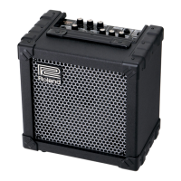
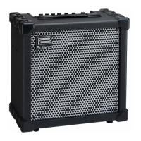
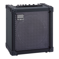
Details on power output, input levels, speakers, and control elements of the amplifier.
Describes the POWER, BATTERY, TUNER, and CHECK/MUTE indicators.
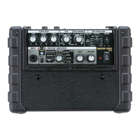
Details the types and functions of all input and output jacks on the unit.
Outlines power requirements, including AC adapter and battery types.
Provides estimated operating times for different output power settings.
Specifies the unit's width, depth, and height in metric and imperial units.
States the weight of the unit, excluding batteries.
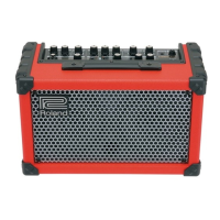
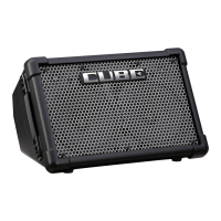
Illustrates and labels the controls on the front panel of the CUBE-STEX amplifier.
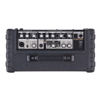
Illustrates and labels the various input/output jacks and power connector on the rear panel.
Lists part codes, names, descriptions, and quantities for components shown in control diagrams.
Presents a visual breakdown of the unit's components with numbered references.
Lists part codes, names, descriptions, and quantities for components in the exploded view.
Provides detailed instructions for safely disassembling the CUBE-STEX unit.
Shows the top of the unit, indicating screw locations for assembly/disassembly.
Shows the bottom of the unit, indicating screw and washer locations.
Details screw locations on the side of the unit.
Illustrates screw locations for the bottom panel and feet.
Shows the front of the unit, highlighting grille attachment screws.
Details screw locations on the rear panel of the unit.
Shows screw locations on the rear panel, including connector area.
Illustrates screw locations on the top panel, including input/output jacks.
Provides a detailed exploded view of internal components and sub-assemblies.
Lists part codes, names, and quantities for the detailed exploded view components.
Details screw points on the front and top panel assembly.
Shows screw points on the rear panel assembly.
Illustrates screw locations and component labels on the top/front panel.
Shows screw points and internal component references on the rear panel.
Shows screw points on the side panel assembly.
Illustrates screw locations on the rear panel assembly.
Illustrates the wiring and signal flow between different internal circuit boards.
Details power distribution circuits and panel board connection schematics.
Lists part codes, names, and connector types for all internal wiring cables.
Details part numbers and descriptions for various cushioning components.
Lists all available service parts categorized by unit section like Casing, Chassis, and Boards.
Lists part codes and descriptions for potentiometers, fuse holders, wiring cables, and screws.
Details miscellaneous items such as battery packs, cushions, and EVA packing.
Lists standard accessories provided with the CUBE-STEX unit.
Procedure to verify the unit's current software version using foot switches.
Detailed steps to access, operate, and quit the unit's diagnostic test modes.
Details the DSP and EEPROM testing process and fault indication.
Guides through testing unit switches and LEDs by performing specific operations.
Procedure for testing and verifying the function of all volume controls.
Steps to test input and output signal levels using external equipment.
Covers testing of MIC/GUITAR, AUX IN, and i-CUBE LINK inputs.
Details testing procedures for LINE OUT, PHONES, and i-CUBE LINK outputs.
Diagrams showing the physical layout of the Main, Audio Input, and Input circuit boards.
Illustrates component placement on the Main Sheet, Audio Input, and Input circuit boards.
Schematic showing power supply, update port, and control signal connections.
Schematic for panel board interfaces and mode setting configurations.
Schematic detailing LINE IN, LINK_IN/AUDIO, and MIC/INST signal processing circuits.
Schematic illustrating power supply regulation and headphone output stages.
Schematic showing circuitry for MIC/GUITAR and AUDIO IN signal paths.
Schematic detailing the LINE OUT and STEREO LINK OUT signal processing circuits.
Schematic showing power supply control, battery charging, and power switching circuits.
Schematic illustrating amplifier power control, mute, and voltage regulation.
Schematic detailing the input stage for AUX and DGND signals.
Shows the connector pinout and external interface for the audio input board.
Schematic for the MIC/INST and MIC/GUITAR input signal processing circuits.
Shows potentiometers and switches connected to the input board's ICs.
Illustrates component placement on Panel L/R, Line Input, and Jack circuit boards.
Schematic detailing the components and connections for the Panel L board.
Diagram showing the layout and connections of potentiometers on the Panel L board.
Schematic detailing the components and connections for the Panel R board.
Schematic detailing the input stage and connections for LINE IN jacks.
Schematic showing wiring for audio jacks, foot switches, and power input.
Diagram showing connections for the PHONES jack and other rear panel connectors.