29
FANTOM-X6
fig.test-lcd1_70
When you press the [8] knob, you will proceed to the all-pixels-displayed test.
The LCD display will show as follows.
fig.test647_70
Verify that there are no missing dots, and that the darkness is consistent.
When you press the [8] button, you will proceed to the all-pixels-off test. The
LCD display will show as follows.
fig.test648_70
Verify that there is no obtrusive dirt or dust.
Press the [8] button to proceed to the next test item.
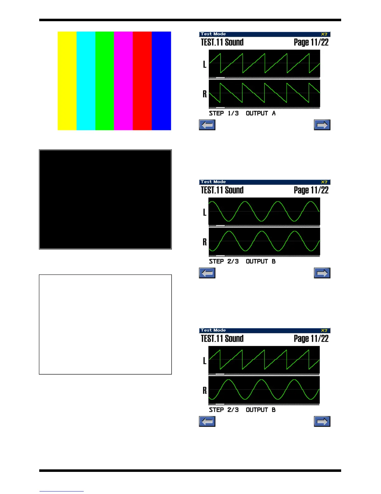
11. Sound test
This tests the audio input/output circuitry.
First you will test the [OUTPUT A L (MONO)] jack and [INPUT L/R] jack
circuitry.
Connect the stereo side of the PCS-31 to the [OUTPUT A L (MONO)] jack,
connect the PCS-31’s monaural L channel to the [INPUT L] jack, and the PCS-
31’s monaural R channel to the [INPUT R] jack. Insert a dummy plug into the
[OUTPUT A R] jack, and turn the [VOLUME OUTPUT] knob and [VOLUME
INPUT] knob all the way toward the right (MAX).
Verify that the LCD display shows a sawtooth wave and another sawtooth
wave (of inverted phase relative to the upper one) below, as follows.
fig.test-sound1_70
Next you will test the circuitry of the [OUTPUT A R] jack.
Connect the stereo side of the PCS-31 to the [OUTPUT A R] jack, connect the
PCS-31’s monaural L channel to the [INPUT L] jack, and connect the PCS-31’s
monaural R channel to the [INPUT R] jack. Turn the [VOLUME OUTPUT]
knob and the [VOLUME INPUT] knob all the way toward the right (MAX).
Verify that the LCD display shows a sine wave above and another sine wave
(of inverted phase relative to the upper one) below, as follows.
fig.test-sound2_70
When you press the [8] button you will proceed to the test of the [OUTPUT B
L/R] jack circuit.
Use an audio cable to connect the [OUTPUT B L] jack to the [INPUT L] jack,
and the [OUTPUT B R] jack to the [INPUT R] jack. Turn the [VOLUME INPUT]
knob all the way toward the right (MAX).
Verify that the LCD display shows a sawtooth wave above and a sine wave
below, as follows.
fig.test-sound3_70
When you press the [8] button you will proceed to the test of the [DIGITAL
INPUT OUTPUT] jacks.
Use a COAXIAL (pin) cable to connect the [DIGITAL INPUT] and [DIGITAL
OUT] jack.
Verify that the LCD display shows a sawtooth wave above and a sine wave
below, as follows.

 Loading...