RC-20 May. 2001
1
SERVICE NOTES
First Edition
Issued by RJA
• Nominal Input Level
INPUT : -20 dBu (variable)
MIC : -40 dBu (variable)
AUX IN : -10 dBu
• Input Impedance
INPUT : 1M ohm
MIC: 1k ohm
AUX IN : 47k ohm
• Nominal Output Level
OUTPUT : -20 dBu
• Output Impedance
1k ohm
• Recommended Load
Impedance
10k ohm or greater
• Internal Memory
Recording Time : 5 min. 30 sec.
(max.)
10 loop phrases + 1 one-shot
phrase (max.)
• Controls
REC/PLAY/OVERDUB Pedal
STOP/TAP TEMPO Pedal
INST Knob
MIC Knob
PHRASE SELECT Knob
GUIDE Knob
LEVEL Knob
REVERSE Button
TAP TEMPO Button
WRITE Button
EXIT Button
AUTO START Button
MODE Button
• Indicators
POWER (serves also as battery
check indicator)
REC
PLAY
OVERDUB
PEAK
PHRASE USED
MEMORY FULL
LOOP QUANTIZE
TAP TEMPO
REVERSE
WRITE
EXIT
AUTO START
INST & MIC
NORMAL
CENTER CANCEL
FLAT AMP SIMULATE
• Connectors
INST Jack
MIC Jack
AUX IN Jack (Stereo miniature
phone type)
PHRASE SHIFT Jack
REVERSE Jack
OUTPUT Jack
• Power
DC 9V : Dry battery (AA type)
x 6, AC Adaptor
• Power Consumption
85 mA (9 V max.)
* Expected battery life under con-
tinuous use:
Carbon : 9 hours
Alkaline : 25 hours
These figures will vary depend-
ing on the actual conditions of
use.
• Dimensions
173 (W) x 158 (D) x 57 (H) mm
6-13/16 (W) x 6-1/4 (D) x 2-1/4
(H) inches
• Weight
1.2 kg / 2 lbs 7 oz (including
batteries)
• Accessories
Owner's Manual English
(#G6017294)
Dry battery <AA type> x 6
(#********)
Sound Library for RC-20 <Sam-
ple Phrase CD-ROM>
(#G2567113)
Sound Library for RC-20 <Sam-
ple Phrase CD LEAFLET>
(#G6017447)
• Options
AC Adaptor (PSA-series)
Foot Switch (FS-5U)
* 0 dBu = 0.775 Vrms
* In the interest of product
improvement, the specifications
and/or appearance of this unit
are subject to change without
prior notice.
SPECIFICATIONS
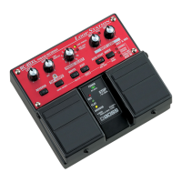
RC-20 : PHRASE RECORDER
Copyright 2001 ROLAND CORPORATION
All rights reserved. No part of this publication may be reproduced in any form without the written permission of ROLAND CORPORATION.
17059083
Printed in Japan 900 (DP)
TABLE OF CONTENTS
SPECIFICATIONS ....................................................................................
LOCATION OF CONTROLS ....................................................................
EXPLODED VIEW ...................................................................................
PARTS LIST ............................................................................................
TEST MODE ............................................................................................
SERIAL DUMP AND UPDATE PROCEDURE .........................................
BLOCK DIAGRAM ...................................................................................
CIRCUIT BOARD (PANEL, JACK) ..........................................................
CIRCUIT DIAGRAM (PANEL) .................................................................
CIRCUIT DIAGRAM (JACK 1-16 LOT) ....................................................
CIRCUIT DIAGRAM (JACK 17 LOT up) ..................................................
CIRCUIT BOARD (CENTER) ..................................................................
CIRCUIT DIAGRAM (CENTER) ..............................................................
Page
..........................................................................................................1
........................................................................................................... 2
........................................................................................................... 3
........................................................................................................... 6
........................................................................................................... 8
......................................................................................................... 11
......................................................................................................... 13
......................................................................................................... 14
......................................................................................................... 16
......................................................................................................... 17
......................................................................................................... 18
......................................................................................................... 19
......................................................................................................... 20