EasyManuals Logo

Roland SDE-3000 Service Notes

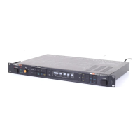
Roland SDE-3000
27 pages
To Next Page IconTo Next Page
To Previous Page IconTo Previous Page
Page #6 background imageLoading...
Page #6 background image
SDE-1000/3000
FEB.
5.1984
CIRCUIT
DESCRIPTIONS
General
Description
SDE-1000/3000,
Digital
Delay
Line,
use
RAMs
as
memory
device
in
which
audio
signals
are
stored
by
means
of
PCM
(Pulse
Coded
Modulation)
method.
The
delay
unit
first
samples
the
input
audio
signal
to
have
a
series
of
discrete
values
of
the
signal
amplitude
at
point.
Each
of
sampled
pulses
is
digitalized
and
stored
into
RAM
cells
as
a
binary
coded
data
which,
when
a
specified
time
passed,
is
read,
restored
to
analog
value,
then
injected
into
audio
path
as
a
delayed
signal.
The
process
can
well
be
compared
to
that
of
conventional
tape
echo
machine
as
shown
in
Fig.
1.
RAM
cells
correspond
to
the
tape
and
the
RAM
accessing
to
a
Record/Play
back
head.
In
operation
R/P
head
first
functions
as
a
playback
head
and
will
read
a
group
of
RAM
cells
being
in
touch
with,
then
quickly
changes
to
a
recording
head
to
record
digital
data
being
fed
from
the
A/D
converter
into
the
same
cells.
The
head
steps
to
the
next
cell
group
and
repeats
the
read
and
write
opera
tions,
then
to
the
third,
fourth
and
so
on
continuously
until
the
time
deter
mined
by
DELAY
TIME
button
comes.
When
the
delay
time
has
passed,
the
head
leaves
the
remaining
cells
unused
and
jumps
to
the
first
cell
group
where
it
reads
the
previously
stored
data
and
writes
the
new
data.
The
number
of
cell
groups
the
head
can
see
is
based
on
DELAY
TIME
setting
and
the
travel
ling
speed
of
the
head
slows
down
one-half
when
in
TIME
X2
mode.
In
other
words,
the
length
of
the
tape
varies
with
Delay
Time
and
the
speed
with
Delay
Time
Range
(also
X1—X1.5
setting
and
MOD
rate).
The
following
description
breaks
major
circuits
down
into
Analog
and
Digital,
starting
with
SDE-1000
circuits
most
of
which
are
also
found
in
SDE-3000,
then
goes
through
the
circuits
featuring
SDE-3000.
One
major
difference
be
tween
two
models
are
their
time
delay
ranges:
SDE-3000
four
times
the
SDE-
1000
in
RAM
memory
capacity.
RAM
MEMORY
CELLS
SDE-1000
See
P.
13
for
SDE-3000
Fig.
1
HEAD
AMP
The
Head
Amp
interfaces
the
unit
wih
a
variety
of
input
signals
so
that
the
unit
can
operate
with
adequate
signal
*
noise
and
without
execessive
limiting
across
the
dynamic
range
of
the
signa
Although
this
amp
has
a
gain
range
of
1
to
24,
VR-6
(INPUT
ATT)
attenuass
the
delay
signal
as
it
is
rotated
from
FCW
position
to
CCW.
The
unit's
overll
gain
is
unity
at
FCW.
NOTE:
Minor
modifications
are
madeon
SDE-1000
head
amp
and
associated
circuits
to
provide
more
headroom
without
sacrificing
tonal
quality
and
sound
level.
Refer
to
Engineering
Chage
in
SDE-1000
section
in
this
manual.
FEEDBACK/MIXING
The
delay
signal
is
mixed
again
with aiew
direct
signal
when
0V
is
placed
on
Q51
gate,
and
out
of
the
delay
line
whn
-14V
is
on
the
gate.
PREEMPHASIS
This
stage
boosts
higher
frequency
corents
to
provide
a
good
S/N
ratio.
GAIN:
unity
at
1kHz
and
2.5
at
10kH
INPUT
jack
1
kHz
TP-2
TIME
X2
OFF
TP-2
TIME
X2
ON
0.2
ms/div
LPF-1
An
'Anti-aliasing
filter
including
tw
filters
of
different
cutoff
point.
Only
one
filter
is
connected
to
the
next
stge
at
a
time.
Pressing
TIME
X2
switch
causes
the
Control
Logic
(IC14,
etc to
place
a
ground
to
the
gate
of
027
and
-14V
to
Q28,
limiting
the
filir's
output
bandwidth
within
10Hz-
8kHz.
Disengaging
the
X2
switch
corlucts
Q28
and
cuts
off
Q27,
extending
the
bandwidth
to
17kHz.
Control
Lgic
also
cuts
off
both
FETs
for
7
sec
after
power
is
first
applied
to
the
un;
and
during
HOLD
ON
mode
or
while
Delay
Time
button
is
manuplated.
*
Aliasing
The
type
of
distortioi
that
is
found
in
"sampled"
signal
pro
cessing
system
when
the
signal
has
frtjuency
components
which
exceed
half
the
sampling
frequency.
COMPRESSOR
This
stage
logarithmically
reduces
trudynamic
range
of
the
signal
before
it
is
digitalized.
NOTE:
For
detailed
descriptions
olS/H,
A/D,
D/A,
Main
Controller
and
RAM,
see
corresponding
sections
in
S
E-3000
description.
SAMPLE
&
HOLD
ICs
5A
and
5B,
together
with
C13
extract
a
portion
of
the
input
signal
at
SAH
rate.
The
sampled
audio
is
fed
through
Q8
to
pin
2
of
IC2
where
it
is
compared
with
12
step
voltages
on
pin
3
to
have
its
analog
voltage
repre
sented
by
digital
code
through
A/D
conversion.
NOTE:
SAH
rate
is
constant
regardless
of
DELAY
TIME
setting,
but
varies
when
TIME
X2,
DELAY
TIME
X1/X1.5
or
MODULATION
is
enabled.
A/D
CONVERTER
The
A/D
Converter
employed
here
is
of
Successive
Approximation
consisting
of
SAR
(Successive
Approximation
Registers
in
IC12,
Main
Controller),
ICs
3
and 4
which
boost
TTL
compatible
to
12V,
RM-1
ladder
resistor
which
adds
a
corresponding
analog
weight
to
individual
bit,
Q9
and
Q10
follower
and
comparator
IC2.
In
operation,
SAR
first
sets
the
highest
bit
(MSB)
register
to
H
(1)
whose
output
is,
after
given
the
highest
voltage
at
RM-1,
compared
with
sampled
audio
at
IC2
input.
If
MSB
is
larger
than
the
sampled
audio,
it is
reset
to
L(0)
by
a
H
from
IC2
(D
IN).
If
smaller,
kept
set
and
applied
once
more
together
with
the
second
highest
bit
register
output
(H)
that
is
one-half
the
highest
in
voltage.
The
process
repeats
for
MSBs
while
the
combination
of
SAR
outputs
is
approaching
to
the
sampled
audio
level.
During
the
process,
D
IN
is
also
transferred
to
RAMs
IC9-IC11
to record
H
or
L
of
all
the
bits
which,
when
grouped
into
12
bits,
are
the
data
of
the
sampled
portion
of
audio
input
signal.

Other manuals for Roland SDE-3000

Questions and Answers:

Question and Answer IconNeed help?

Do you have a question about the Roland SDE-3000 and is the answer not in the manual?

Roland SDE-3000 Specifications

General IconGeneral
TypeDigital Delay
Output Impedance1 kOhm
Inputs1/4" phone jack
Outputs1/4" phone jack
Total Harmonic Distortion0.05%
Power SupplyAC 117 V

Related product manuals