10
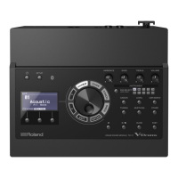
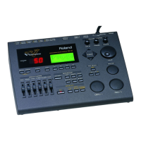
TD-12 MIDI Implementation
●V-LINK message
❍V-LINK ON
Transmitted when entering V-LINK mode.
Status Data byte Status
F0H 41H, dev, 00H, 51H, 12H, F7H
10H, 00H, 00H, 01H,
nnH, 10H, 01H, sum
Byte Explanation
F0H Exclusive status
41H ID number (Roland)
dev Device ID (00H - 1FH, 7FH (1 - 32, 128)) Initial value is 10H (17)
00H Model ID #1 (V-LINK)
51H Model ID #2 (V-LINK)
12H Command ID (DT1)
10H 00H 00H Address
01H V-LINK ON
nnH Clip Control Rx MIDI Ch. (00H - 0FH (ch.1 - ch.16))
Initial value is 0FH (ch.16)
10H Color Control Rx MIDI Ch. (OFF)
01H Note Message Enabled (ON)
sum Checksum
F7H EOX (End of Exclusive)
* Setting [SETUP]-[V-LINK] V-LINK Switch to ON puts the unit in V-LINK
mode.
* The [SETUP]-[V-LINK] V-LINK Device ID setting is used as the Device ID.
* The [SETUP]-[V-LINK] V-LINK MIDI Ch setting is used as the Clip Control Rx
MIDI Ch.
* Only the Clip Control Rx MIDI Ch address (10H 00H 01H) and data are
transmitted when the [SETUP]-[V-LINK] V-LINK MIDI Ch setting is made in V-
LINK mode.
❍V-LINK OFF
Transmitted when exiting V-LINK mode.
Status Data byte Status
F0H 41H, dev, 00H, 51H, 12H, F7H
10H, 00H, 00H, 00H, 70H
Byte Explanation
F0H Exclusive status
41H ID number (Roland)
dev Device ID (00H - 1FH, 7FH (1 - 32, 128)) Initial value is 10H (17)
00H Model ID #1 (V-LINK)
51H Model ID #2 (V-LINK)
12H Command ID (DT1)
10H 00H 00H Address
00H V-LINK OFF
70H Checksum
F7H EOX (End of Exclusive)
* Setting [SETUP]-[V-LINK] V-LINK Switch to OFF causes the unit to exit V-
LINK mode.
* The [SETUP]-[V-LINK] V-LINK Device ID setting is used as the Device ID.
3. Parameter address map
This map indicates Address and Parameter which can be transferred using “Data
Set 1 (DT1)”.
All the numbers of address are indicated in 7-bit Hexadecimal-form.
■Parameter Address Block
TD-12 (Model ID = 00H 00H 09H)
+———————————————————————————————————————————————————————————————————————+
| Start | |
| address | Description |
|—————————————+—————————————————————————————————————————————————————————|
| 70 00 00 00 | SETUP (Bulk) (*1) |
|—————————————+—————————————————————————————————————————————————————————|
| 71 00 00 00 | TRIGGER BANK 1 (Bulk) |
| 71 01 00 00 | TRIGGER BANK 2 (Bulk) |
| 71 02 00 00 | TRIGGER BANK 3 (Bulk) |
| 71 03 00 00 | TRIGGER BANK 4 (Bulk) |
|—————————————+—————————————————————————————————————————————————————————|
| 72 00 00 00 | DRUM KIT 1 (Bulk) |
| 72 01 00 00 | DRUM KIT 2 (Bulk) |
| : | |
| 72 31 00 00 | DRUM KIT 50 (Bulk) |
|—————————————+—————————————————————————————————————————————————————————|
| 73 00 00 00 | PERCUSSION SET 1 (Bulk) |
| 73 01 00 00 | PERCUSSION SET 2 (Bulk) |
| : | |
| 73 07 00 00 | PERCUSSION SET 8 (Bulk) |
|—————————————+—————————————————————————————————————————————————————————|
| 74 00 00 00 | PATTERN INFORMATION (Bulk) (*2) |
| 75 00 00 00 | PATTERN DATA (Bulk) |
+———————————————————————————————————————————————————————————————————————+
*1: Except Device ID and LCD Contrast
*2: User Patterns U151 - U250
 Loading...
