SERVICE NOTES
Issued by RJA
Copyright © 2004 ROLAND CORPORATION
All rights reserved. No part of this publication may be reproduced in any form without the written permission
of ROLAND CORPORATION.
Printed in Japan (0500) (TP)17058228E0
Feb.2004 TD-20
TABLE OF CONTENTS
CAUTIONARY NOTES ...................................................2
SPECIFICATIONS.............................................................3
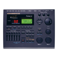
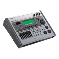
LOCATION OF CONTROLS ..........................................4
LOCATION OF CONTROLS PARTS LIST ...................5
EXPLODED VIEW ............................................................6
EXPLODED VIEW PARTS LIST .....................................7
WIRING DIAGRAM.........................................................8
PARTS LIST........................................................................9
CHECKING THE VERSION NUMBER.......................17
INITIALIZING (FORMATTING) THE MEMORY
CARD................................................................................17
USERS DATA SAVE AND LOAD................................17
TEST MODE.....................................................................19
RESTORING THE FACTORY SETTINGS...................23
SYSTEM SOFTWARE UPDATE PROCEDURE .........23
BLOCK DIAGRAM.........................................................27
CIRCUIT BOARD (MAIN) ............................................30
CIRCUIT DIAGRAM (MAIN) ......................................34
CIRCUIT BOARD (PANEL-U&L/MASTER/
VOLUME) ........................................................................52
CIRCUIT DIAGRAM (PANEL-U) ...............................56
CIRCUIT DIAGRAM (PANEL-L) ................................58
CIRCUIT DIAGRAM (MASTER) .................................60
CIRCUIT DIAGRAM (VOLUME) ................................62
CIRCUIT BOARD (COAXAL/TRIG/LCD CN) ........64
CIRCUIT DIAGRAM (COAXIAL) ...............................68
CIRCUIT DIAGRAM (TRIG) ........................................70
CIRCUIT DIAGRAM (LCD CN) ..................................76
ERROR MESSAGES ........................................................77
Revise Information
Oct 14, 2008(p. 2) CAUTIONARY NOTES added
(p. 17, p. 19, p. 23) Important notes on different program versions added
(p. 24) Process of Updating the TD-20 corrected, with partial deletions