M
AINTENANCE AND
T
ROUBLESHOOTING
4-2
June 1997 Rosemount Analytical 748332-DNGA 2000 Non-Dispersive Infrared Analyzer
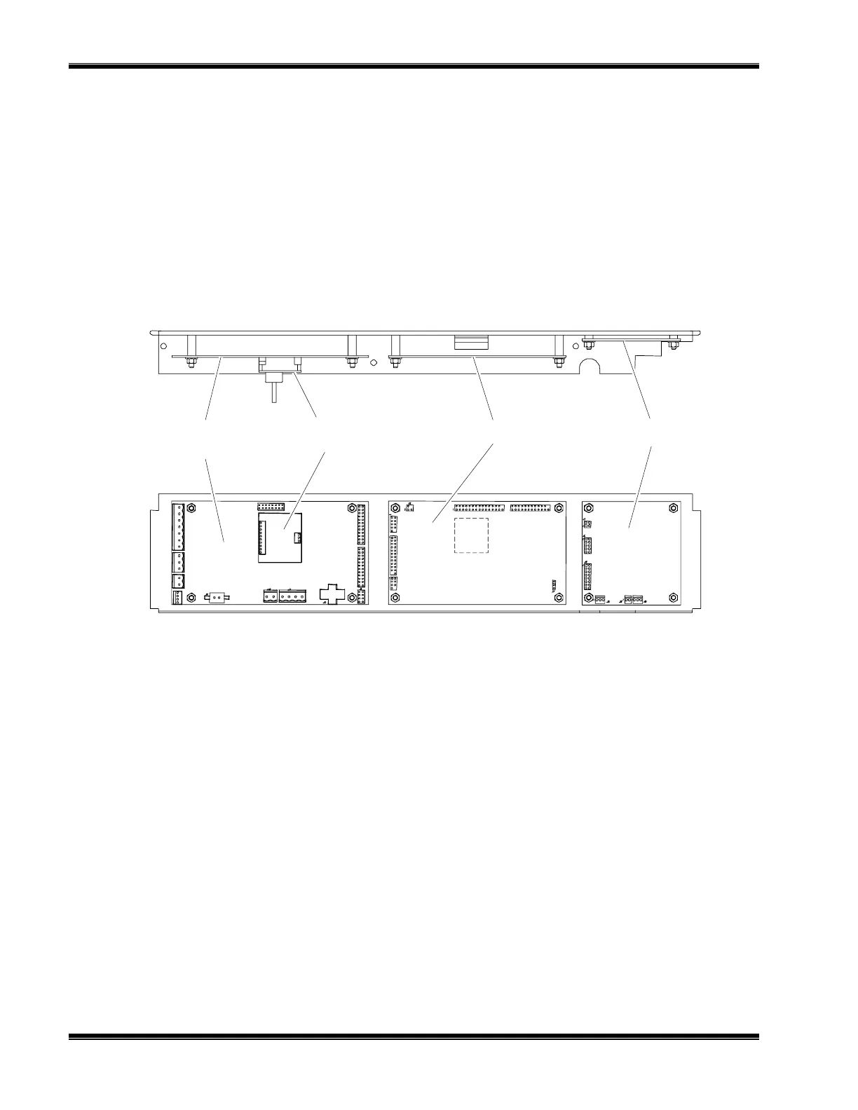
Power Supply
Board
Pressure
Compensation Board
Micro Board Signal Board
TOP VIEW
SIDE VIEW
4.2 PCB REPLACEMENT
Refer to Figure 4-1 for locations of the Signal, Micro, Power Supply, Oscillator and
optional Pressure Compensation boards.
All PCBs, except the Oscillator Board and the LON Power Board, are secured to a
side of the analyzer module that folds out while interconnect wiring is still in place.
Remove the securing screws and fold out the entire panel.
F
IGURE
4-1. P
RINTED
C
IRCUIT
B
OARD
F
OLD
-O
UT
P
ANEL
V
IEWS
To remove a particular board on the fold-out panel, label and unplug all interconnect
wiring, and remove securing hardware. (See Figure 4-1.) Do the reverse to install a
new board. Use caution when installing connectors by observing correct position
(polarity) and alignment of pins.
4.3 POWER FUSE REPLACEMENT
Remove power to the Analyzer Module prior to fuse replacement. To replace the
Power Fuse, view the front panel of the Analyzer Module, as shown in Figure 2-4, and
push and turn the fuseholder cap 1/4 turn counterclockwise. Remove and replace the
fuse as required.
4.4 MODULE FAN REPLACEMENT
The Analyzer Module fan assembly is disassembled as shown in Figure 4-2. Before
doing so, though, the entire optical bench must be removed. See Figure 4-4.