M
AINTENANCE AND
T
ROUBLESHOOTING
4-4
June 1997 Rosemount Analytical 748332-DNGA 2000 Non-Dispersive Infrared Analyzer
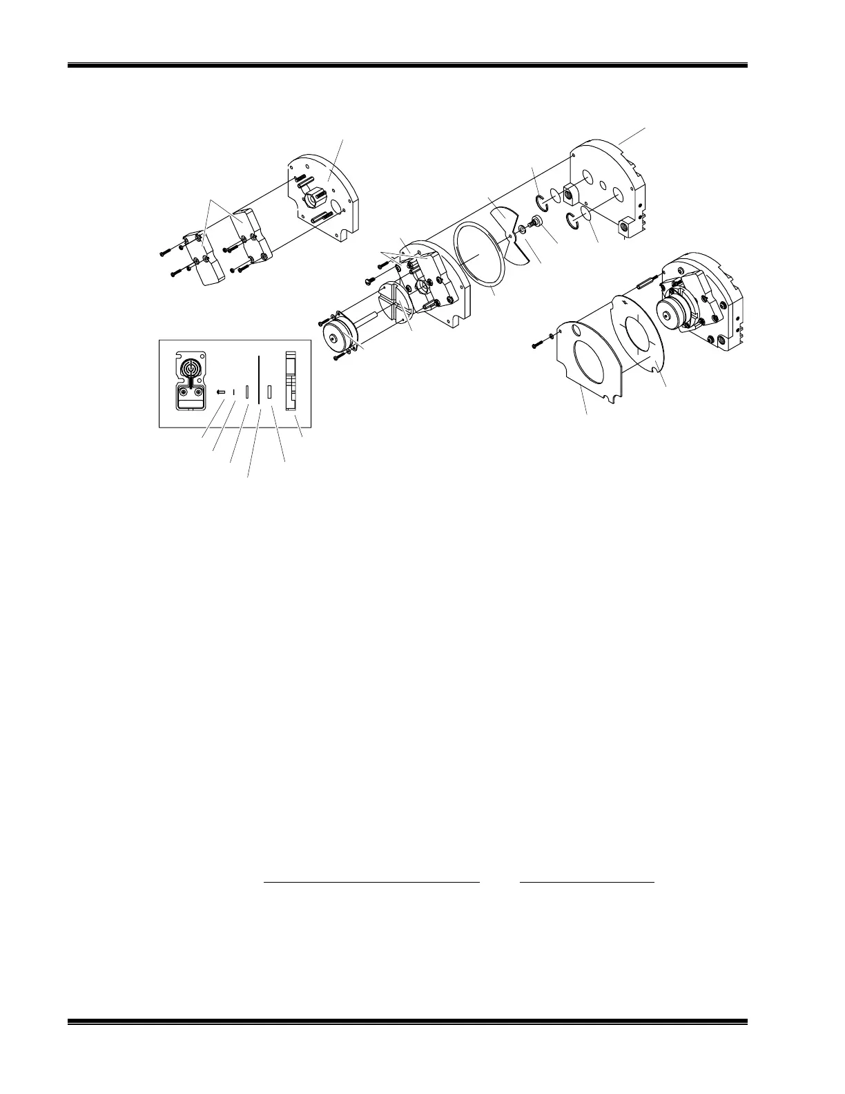
F
IGURE
4-3. M
OTOR
/S
OURCE
A
SSEMBLY
4.9 CASE TEMPERATURE SENSOR REPLACEMENT
Case Temperature Sensor is attached to the motor source assembly. To replace this
sensor, cut the Ty-Rap
binder and disconnect the sensor connector. Reverse these
instructions by reconnecting the new sensor and attaching with a new Ty-Rap
.
4.10 THERMAL FUSE REPLACEMENT
Disassemble and reassemble the Detector block according to Figure 4-6 to replace
the Detector Thermal Fuse.
4.11 OSCILLATOR TUNE/SOURCE BALANCE SHUTTER
ADJUSTMENT
The Analyzer Module is calibrated, tuned and balanced at the factory. If the diagnostic
values for oscillator tune and detector signals are within
±
5 % of the factory settings
(see Figure 3-13, in Primary Variable Parameters and Modulation Check menus), no
adjustment is necessary. If not, see Figure 4-4 and 4-5 for Oscillator Tune and Source
Balance Shutter adjustments, and do the following:
Housing Assembly
Screw
Lock Washer
Insulator
Source
Insulator
Source Case
Source Assemblies
(see detail below)
Ref - Housing
Assembly
Motor
Ref - Source
Assemblies
Motor Plate
O-Ring
Chopper
Blade
Nylon
Washer
Screw
Retaining
Ring
Screen Filter
(optional)
Source Buffer
Source Gasket
Dual Cap
Assembly