C
ONTENTS
748332-D Rosemount Analytical June 1997
iii
NGA Non-Dispersive Infrared Analyzer
I
NFRARED
A
NALYZER
D
ATA
S
HEET
G
ENERAL
P
RECAUTIONS FOR
H
ANDLING
& S
TORING
H
IGH
P
RESSURE
C
YLINDERS
W
ARRANTY
F
IELD
S
ERVICE AND
R
EPAIR
F
ACILITIES
F
IGURES
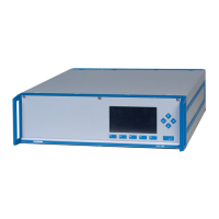
1-1 NGA 2000 NDIR Analyzer Module (Typical - Actual configuration May
Vary)..............................................................................................1-3
1-2 NDIR Technology ......................................................................................1-4
2-1 Analyzer Module Installation Into Instrument Platform...............................2-1
2-2 Outline and Mounting Dimensions.............................................................2-4
2-3 NDIR Back Panel.......................................................................................2-5
2-4 NDIR Front Panel Electrical Connections..................................................2-5
2-5 NDIR Wiring Diagram ................................................................................2-6
3-1 Run Mode Display .....................................................................................3-3
3-2 Main Menu Display ....................................................................................3-3
3-3 Basic Controls Menu..................................................................................3-3
3-4 Expert Controls and Setup Menu...............................................................3-4
3-5 Technical Level Configuration Menu .........................................................3-4
3-6 Typical Help Screen...................................................................................3-4
3-7 Typical Linearization Curve, Linearizer OFF..............................................3-7
3-8 Operator-Determined Linearization Curve (Normalized)............................3-7
3-9 Display Screens (1 of 5) ............................................................................3-10
3-10 Display Screens (2 of 5) ............................................................................3-11
3-11 Display Screens (3 of 5) ............................................................................3-12
3-12 Display Screens (4 of 5) ............................................................................3-13
3-13 Display Screens (5 of 5) ............................................................................3-14
4-1 Printed Circuit Board Fold-Out Panel Views..............................................4-2
4-2 Module Fan Assembly...............................................................................4-3
4-3 Motor/Source Assembly.............................................................................4-4
4-4 Cell, PCB Assembly (Exploded View)........................................................4-6
4-5 Oscillator Tune, Source Balance Shutter Adjustments..............................4-7
4-6 Detector Block (Exploded View) ................................................................4-7
4-7 Cell Disassembly .......................................................................................4-9
T
ABLES
2-1. Cell Purging Times at Atmospheric Sample Pressure...............................2-2
3-1 NDIR Analyzer Module Alarms..................................................................3-6
4-1 Cell Desiccant............................................................................................4-10