Do you have a question about the Rosemount 54E and is the answer not in the manual?
Essential safety and usage instructions.
Critical warnings regarding electrical shock risks during installation and servicing.
Product usage restriction notice for specific environments.
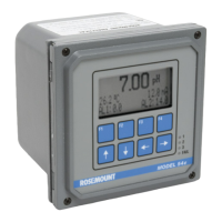
Detailed technical specifications including physical, electrical, and environmental characteristics.
Instructions for connecting the controller to AC or DC power sources.
Procedures for connecting pH sensors, including preamp location and cable dressing.
Safety warnings and important notes before performing calibration procedures.
Procedure to ensure accurate temperature measurement and its effect on pH readings.
Step-by-step guide for auto-recognizing buffers and stabilizing readings for calibration.
Procedure for manual buffer value entry and calibration without auto-recognition.
Method for standardizing the controller using a process grab sample.
Guide to adjusting the setpoints for the controller's three alarm relays.
How to adjust setpoints for PID control mode outputs.
Procedure for reranging the 4-20 mA current outputs for normal mode.
Configuring output measurement, control mode, and setup parameters.
Configuring alarm activation methods, modes, and setup details.
Configuring automatic buffer recognition and stabilization for calibration.
General guidelines and specific procedures for troubleshooting sensor and circuit issues.
| Output | 4–20 mA HART |
|---|---|
| Power Supply | 24 V DC |
| Communication Protocol | HART |
| Enclosure | Aluminum |
| Display | LCD |
| Enclosure Rating | IP66 |