Do you have a question about the Rosemount 3095 and is the answer not in the manual?
Guide on how to use the manual and its structure.
Highlights safety precautions for personnel performing operations.
Special precautions for safety during installation operations.
Overview of the Model 3095 Multivariable Level Controller system.
Outlines tasks for successful installation and reviews the installation flowchart.
Details the process of unpacking the controller and checking contents.
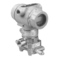
Identifies major components of the controller system and the unit.
Explains controller configuration on a bench using a HART Communicator.
Discusses factors for accurate measurement and proper controller installation.
Covers mounting options, weight, and bolt installation guidelines for the controller.
Illustrates example installations for various tank configurations.
Addresses flange orientation, venting, and temperature limits for process connections.
Discusses piping between the process and controller for accurate pressure transfer.
Details considerations for optimizing performance with diaphragm seals.
Guidelines for mounting the controller to minimize environmental impacts.
Explains how to rotate the electronics housing for better field access.
Details the steps for mounting, connecting to process, and wiring the controller.
Explains how the controller calculates level using DP, density, and gravity.
Describes the multi-variable sensor technology and factory calibration.
Details the PID controller features and algorithm.
Explains the Autotuner feature for optimal tuning parameters.
Explains the ABC algorithm to eliminate limit cycling.
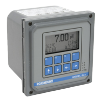
Describes the optional LOI for local indication and operation.
Allows the controller to maintain control during sensor failure.
Outlines the four major tasks for configuring the controller.
Tasks to set up the controller for a specific process, including density and units.
Determines controller height based on installation type and location.
Configures process control, including range values, control type, and action.
Calibrates the level calculation against the actual tank level.
Sets PID parameters like gain, reset, and rate for optimal control.
Highlights safety precautions for maintenance operations.
Procedures for verifying device hardware and process connections.
Identifies causes and solutions for communication issues with HART Communicator.
Explains critical alarms and how they affect output.
General information before disassembling the device.
Information on the process for returning materials to Rosemount.
Details service, sensor, output, power supply, and load limitations.
Specifies level and temperature accuracy, stability, and effects.
Covers electrical and process connections, materials, and weight.
Provides codes for configuring and ordering the Level Controller.
Introduces using the HART Communicator with the Level Controller.
Safety precautions when using the HART communicator.
Describes the action, function, alphanumeric, and shift keys.
Explains the menu structure and options of the HART Communicator.
Lists messages from the HART Communicator and their descriptions.
Safety precautions related to accessories and options.
Details available accessories like diaphragm seals and manifolds.
Explains optional features like Auto-Tuning and Local Operator Interface.
Provides explosion-proof drawing details for Factory Mutual certification.
Provides explosion-proof drawing details for CSA certification.
| Hazardous Area Certifications | ATEX, IECEx, FM, CSA |
|---|---|
| Output Signal | 4-20 mA, HART |
| Process Temperature Limits | -40 to 185°F (-40 to 85°C) |
| Ambient Temperature Limits | -40 to 185°F (-40 to 85°C) |
| Housing Material | Aluminum |
| Outputs | 4-20 mA HART |
| Communication Protocol | HART |
| Enclosure Rating | IP66, NEMA 4X |
| Power Supply | 10.5 to 42 V DC |