Rosemount Model 3095 Multivariable
™
Level Controller
2-18
ELECTRICAL
CONSIDERATIONS
The signal terminals are located in a compartment of the electronics
housing separate from the controller electronics. Figure 2-11 illustrates
power supply load limitations for the controller.
The dc power supply should provide power with less than 2% ripple.
The total resistance load is the sum of the resistance of the signal leads
and the load resistor, actuator, indicator, and related pieces. Note that
the resistance of intrinsic safety barriers, if used, must be included.
NOTE
A loop resistance between 250–1100 ohms inclusive is required to
communicate with a HART Communicator. With 250 ohms of loop
resistance, a power supply voltage of at least 16.5 V dc is required.
Quick troubleshooting check: there must be at least 11.0 V dc across the
controller terminals.
If a single power supply is used to power more than one Level
Controller, the power supply used, and circuitry common to the
controllers, should not have more than 20 ohms of impedance at 1200 Hz.
For CSA approval, power supply must not exceed 42.4 V dc.
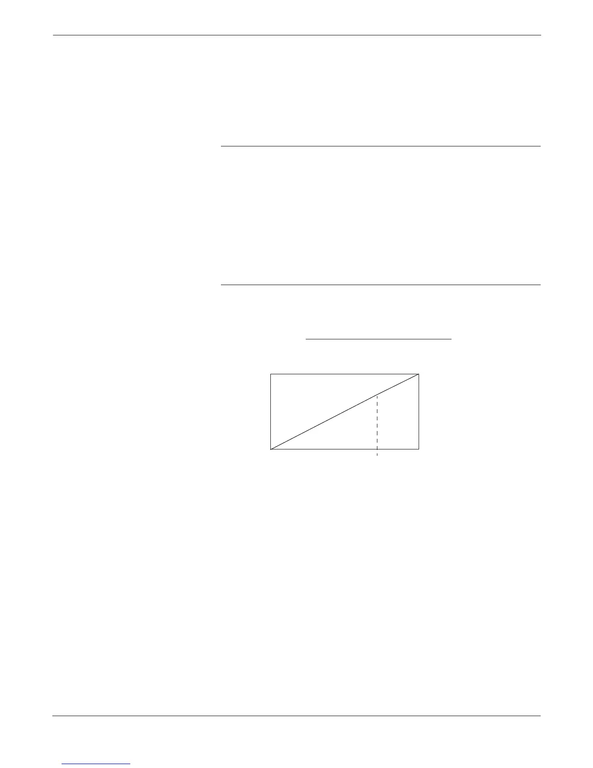
FIGURE 2-11. Power Supply
Load Limitations.
2000
0
11.0 16.5
4–20 mA dc
55
Load (Ohms)
Operating Region
HART protocol communication requires a loop resistance value
between 250–1100 ohms, inclusive.
35.2
Loop resistance is determined by the voltage level of the external power supply, as described by:
Max. Loop Resistance = Power Supply Voltage–11.0–Actuator Voltage
(1)
0.022
Power Supply Voltage
42.4
(2)
(1) Actuator Voltage is the maximum voltage drop across the actuator device.
(1) For CSA approval, power supply must not exceed 42.4 V dc.
3051-0103A