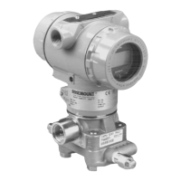
Rosemount Model 3095 Multivariable
™
Level Controller
5-16
Reassemble the Process
Sensor Body
1. Visually inspect the Teflon sensor module O-rings. If the O-rings
are undamaged, they can be re-used. If the O-rings show signs of
damage, such as nicks or cuts, or if there is any doubt about their
sealing ability, replace them with new O-rings.
• Remove the damaged O-rings by carefully prying them from
the O-ring grooves. Take care not to damage the surface of the
isolating diaphragm during this process.
• Replace the damaged O-rings by fitting new O-rings into the
O-ring grooves.
2. Install the process flange on the sensor module. To hold the
process flange in place, install the two hex head alignment
screws. These screws are not pressure retaining and need
only be finger tight. Do not overtighten; this will affect the
module/flange alignment.
• Install the appropriate flange bolts using Figure 2-8 on page
2-12 as a reference:
• For installations requiring a ¼–18 NPT mounting, install the
four 1.75-inch process flange bolts. First, finger-tighten the
bolts. Then tighten the bolts incrementally in a cross pattern
until they are securely tightened to 650 in-lb (300 in-lb for
stainless steel bolts). After tightening, the bolts should
protrude through the top of the module housing.
• For installations requiring a ½–14 NPT mounting, hold the
optional flange adapters and flange adapter O-rings in place
while finger-tightening the four 2.88-inch process flange/
adapter bolts. Tighten the bolts in a cross pattern following
the procedure outlined above. (Use two 2.88- inch bolts and two
1.75-inch bolts for gage pressure configurations.) After
tightening, the bolts should protrude through the top of the
module housing. If the bolts do not extend all the way through
the module housing, you have used a bolt of incorrect length.
Replace the bolt with one of the correct length, and repeat
the procedure.
• For installations with a three-valve manifold, align the process
flange with the three-valve manifold. Install the four 2.25-inch
manifold flange bolts following the procedure outlined above.
After tightening, the bolts should protrude through the top of
the module housing. If the bolts do not extend all the way
through the module housing, you have used a bolt of incorrect
length. Replace the bolt with one of the correct length, and
repeat the procedure. Optional flange adapters can be installed
on the process end of the three-valve manifold using the
1.75-inch flange bolts supplied with the device.
3. If the Teflon sensor module O-rings have been replaced, the
flange bolts should be re-torqued after installation to compensate
for cold flow.
4. Follow these steps to install the drain/vent valve:
• Apply sealing tape to the threads on the seat. Starting at the
base of the valve with the threaded end pointing toward the
installer, apply two clockwise turns of the sealing tape.
• Take care to orient the opening on the valve so that process
fluid will drain toward the ground and away from personnel
when the valve is opened.
• Tighten the drain/vent valve to 250 in-lb.