6-5
Specifications and Reference Data
PHYSICAL
SPECIFICATIONS
Electrical Connections
½–14 NPT, M20 3 1.5 (CM20), PG 13.5.
Process Connections
Controller: ¼–18 NPT on 2
1
/8-in. centers.
½–14 NPT on 2-, 2
1
/8-, or 2¼-in. centers with optional flange adapters.
Process Wetted Parts
Isolating Diaphragms
316L SST or Hastelloy C-276
®
.
Drain/Vent Valves
316 SST or Hastelloy C
®
.
Flanges
Plated carbon steel, 316 SST, or Hastelloy C.
Wetted O-rings
Glass-Filled TFE.
Level Flange and Seal Options
2-inch Stainless Steel ANSI Class 150 Flange
Flange Style Code 0 and Option Code FA.
2-inch Stainless Steel ANSI Class 300 Flange
Flange Style Code 0 and Option Code FB.
3-inch Stainless Steel ANSI Class 150 Flange
Flange Style Code 0 and Option Code FC.
3-inch Stainless Steel ANSI Class 300 Flange
Flange Style Code 0 and Option Code FD.
DIN DN 50 PN 40 Stainless Steel Flange
Flange Style Code 0 and Option Code FP.
DIN DN 80 PN 40 Stainless Steel Flange
Flange Style Code 0 and Option Code FQ.
Remote Seal
Flange Style Code 0 and Option Code S1 or S2. Refer to Model 1199
Remote Seals Product Data Sheet PDS 4016.
RTD
Process connection varies depending on RTD physical specifications.
Non-Wetted Parts
Electronics Housing
Low copper aluminum or optional 316 SST.
Bolts
Plated carbon steel per ASTM A449, Grade 5;
or austenitic 316 SST.
Fill Fluid
Silicone oil.
Paint
Polyurethane.
O-rings
Buna-N.
Weight
Component Weight in lb (kg)
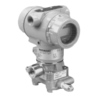
Model 3095 Level Controller
SST Mounting Bracket
12 ft (3.66 m) RTD Shielded Cable
12 ft (3.66 m) RTD Armored Cable
24 ft (7.32 m) RTD Shielded Cable
24 ft (7.32 m) RTD Armored Cable
6.0 (2.7)
1.0 (0.4)
0.5 (0.2)
1.1 (0.5)
1.0 (0.4)
2.2 (1.0)