2-17
Level Controller Overview and Installation
Process Considerations
Level Controller process connections on the controller flange are ¼–18
NPT. Flange adapter unions with ½–14 NPT connections are available as
options. These are Class 2 threads; use your plant-approved lubricant or
sealant when making the process connections. The process connections
on the controller flange are on 2
1
/8-inch (54-mm) centers to allow direct
mounting to a three- or five-valve manifold. By rotating one or both of
the flange adapters, connection centers of 2, 2
1
/8, or 2¼ inches (51, 54,
or 57 mm) may be obtained.
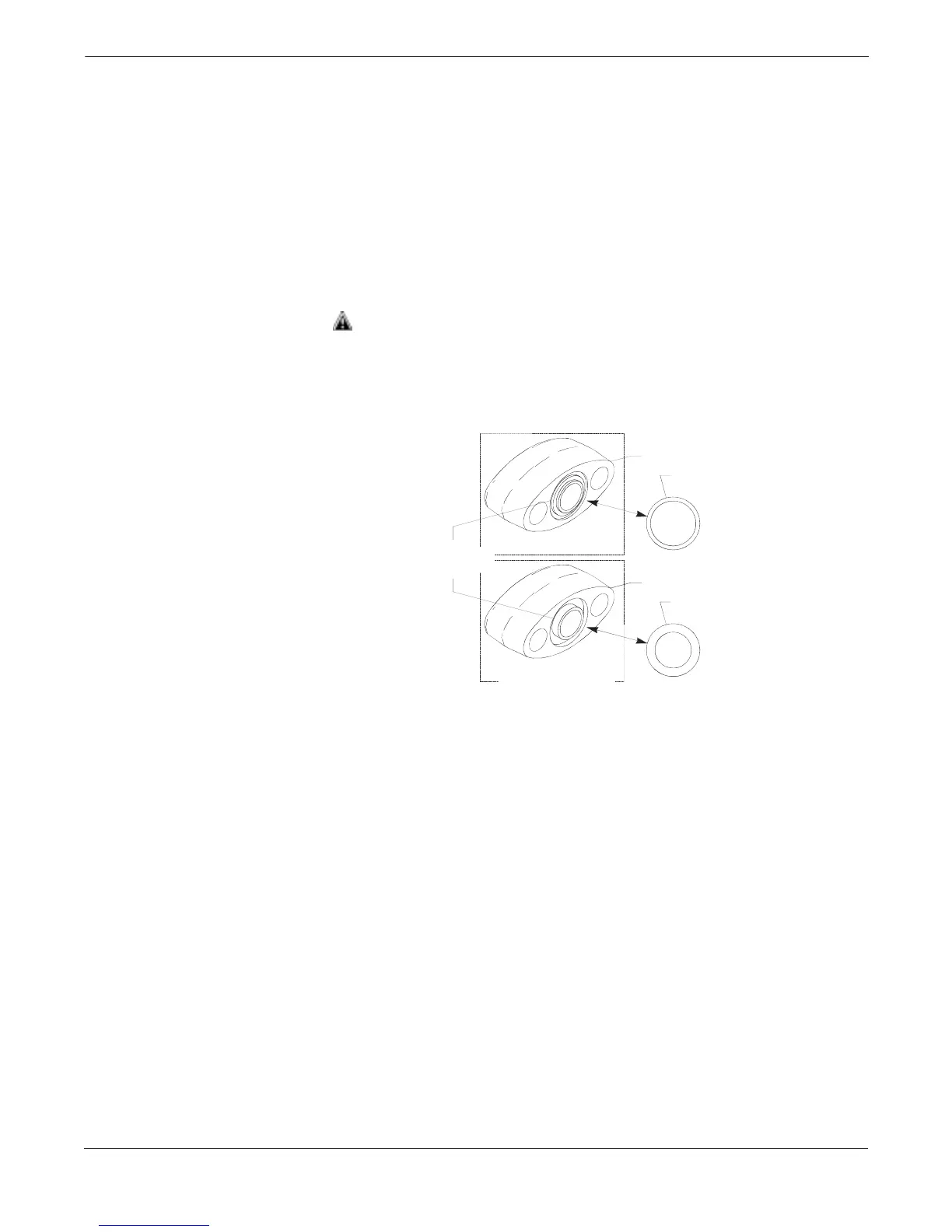
There are two styles of Rosemount flange adapters, each requiring a
unique O-ring, as shown below. Each flange adapter is distinguished
by its unique groove. Use only the O-ring designed to seal with the
corresponding flange adapter.
Use only the O-ring designed to seal with the corresponding flange
adapter. Failure to install proper flange adapter O-rings can cause
process leaks.
FIGURE 2-10. Flange Adapter O-rings.
When compressed, Teflon
®
O-rings tend to cold flow, which aids in their
sealing capabilities. Whenever flanges or adapters are removed, visually
inspect the Teflon O-rings. Replace them if there are any signs of
damage, such as nicks or cuts. If they are undamaged, they can be
reused. If the O-rings are replaced, the flange bolts may need to be
retorqued after installation to compensate for cold flow. Refer to the
process sensor body reassembly procedure on page 5-16.
Unique O-ring
Grooves
MODEL 3051/2024/3001/3095/Level Controller
MODEL 1151
Flange Adapter
O-ring
Flange Adapter
O-ring
3051-0569A01A