Section
6-1
6 Level Controller Specifications
and Reference Data
FUNCTIONAL
SPECIFICATIONS
Service
Liquid level measurement and control.
Differential Sensor
Ranges
Code 2: 0–2.5 to 0–250 inH
2
O (0–0.62 to 0–62.2 kPa).
Code 3: 0–10 to 0–830 inH
2
O (0–2.48 to 0–206 kPa).
Limits
Code 2: –250 to 250 inH
2
O (–62.2 to 62.2 kPa).
Code 3: –830 to 830 inH
2
O (–206 to 206 kPa).
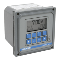
Output
Two-wire 4–20 mA liquid level control signal with digital signal based
on HART protocol.
Power Supply
External power supply required. Controller operates on terminal
voltage of 11–55 V dc.
Humidity Limits
0–100% relative humidity.
Overpressure Limit
0 psia to a maximum of 1,600 psia (11032 kPa).
Static Pressure Limit
Operates within specifications between static line pressures of 0.0 psia
through 800 psia (5516 kPa) maximum.
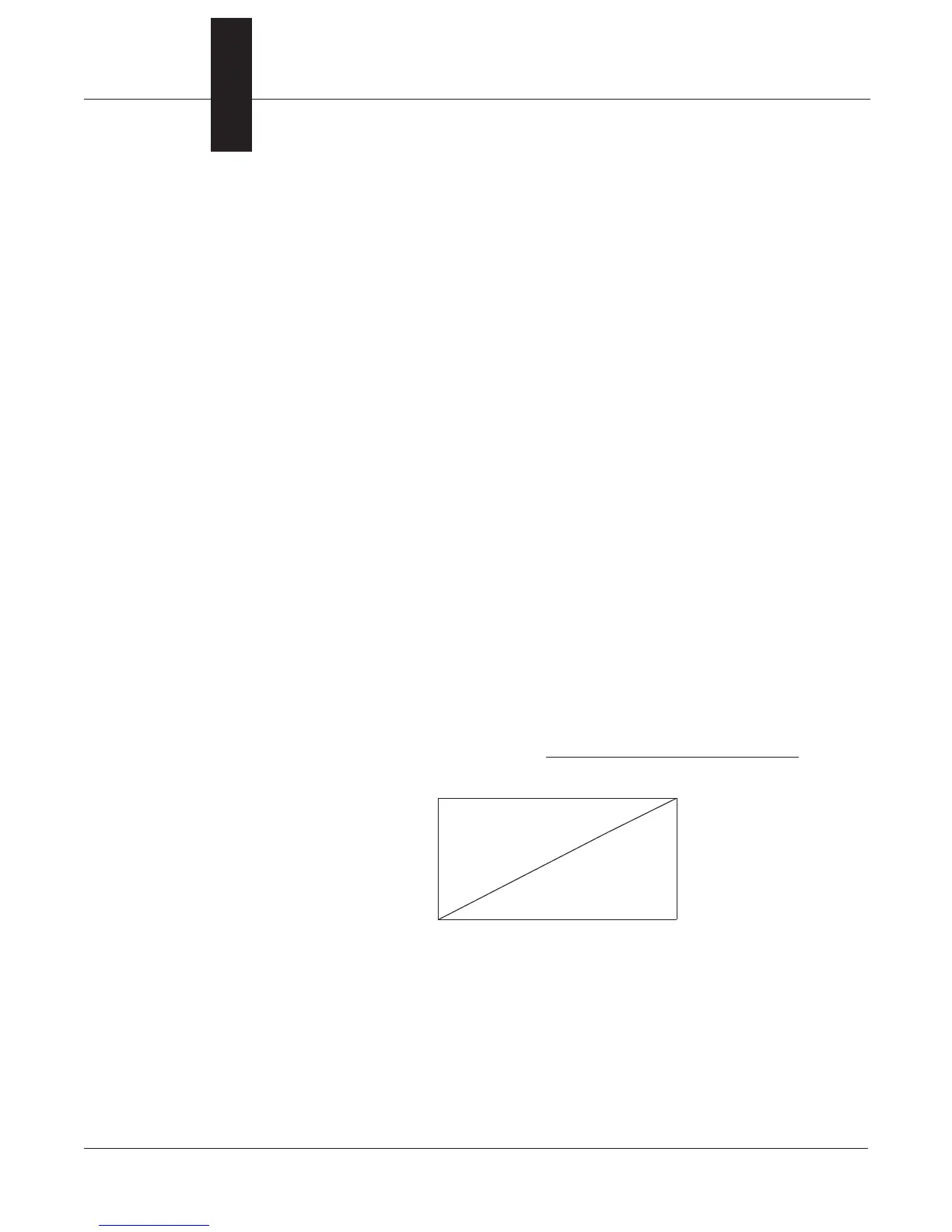
Load Limitations
Loop resistance is determined by the voltage level of the external power
supply, as described by:
2000
0
11.
4–20 mA dc
55
Load (Ohms)
HART protocol communication requires a loop resistance value between
250–1100 ohms, inclusive.
(1)
Control Element Voltage is the maximum voltage drop across the Control
Element.
Max. Loop Resistance = Power Supply Voltage – 11.0 – Actuator Voltage
(1)
0.022
Power Supply Voltage Across Terminals – Actuator Voltage