Do you have a question about the Rosemount 8712E and is the answer not in the manual?
Provides guidelines for careful handling and transport of the flowmeter system.
Covers gasket selection and flange bolt tightening procedures for flanged sensors.
Details gasket placement, alignment spacers, and bolt tightening for wafer sensors.
Outlines gasket requirements and alignment/bolting practices for sanitary sensors.
Determines appropriate grounding methods based on pipe type and installation.
Details requirements for individual and combination cables connecting transmitter and sensor.
| Category | Measuring Instruments |
|---|---|
| Manufacturer | Emerson |
| Model | 8712E |
| Flow Rate Range | 0.1 to 12 m/s |
| Communication Protocol | HART, FOUNDATION Fieldbus, Profibus PA |
| Measurement Principle | Electromagnetic |
| Output Signal | 4-20 mA, HART |
| Process Temperature Range | -40 to 150 °C |
| Electrical Connection | M20 |
| Enclosure Rating | IP67 |
| Power Supply | 24 V DC |
| Enclosure | Stainless Steel |
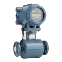
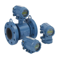
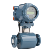
| Product Type | Electromagnetic Flow Meter |



 Loading...