Do you have a question about the Rosemount 8732C and is the answer not in the manual?
Defines the manual's purpose and scope for the Rosemount Model 8732C.
Explains the components and basic operation of the magnetic flowmeter system.
Provides essential safety precautions for working with the flowmeter system.
Overview of the installation procedures for the Model 8732C.
Highlights safety precautions relevant to installation procedures.
Covers identifying options, configurations, and necessary preparations before installation.
Details the function and setting of hardware switches for the transmitter.
Discusses mounting site requirements and physical layout for the transmitter.
Outlines standards and requirements for electrical connections and power supply.
Provides critical notes regarding installation category, wire requirements, and disconnects.
Details the mechanical and electrical steps for installing the flowmeter system.
Covers flowtube mounting, calibration, and upstream/downstream piping requirements.
Explains vertical and horizontal installation guidelines for optimal performance.
Details grounding methods for Model 8705 flowtubes to ensure accurate measurements.
Provides step-by-step instructions for connecting the transmitter to the power source.
Outlines the essential parameters required for initiating basic flowmeter system start-up.
Offers a guide to check new installations and diagnose potential malfunctions.
Describes the standard configuration for containing process fluid within the flowtube housing.
Introduces the LOI as a communications center for transmitter functions.
Highlights safety precautions specific to the LOI operation.
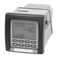
Details the LOI display, keys, and their respective functions for parameter control.
Explains how to enter numerical and alphabetical data using the LOI keypad.
Illustrates the navigation structure and available menus within the LOI.
Lists error messages displayed on the LOI and their corrective actions.
Overview of software functions for configuring transmitter output.
Highlights safety precautions relevant to transmitter function configuration.
Guides on reviewing factory set configuration data for accuracy.
Covers essential settings like Units, Line Size, and Upper Range Value.
Explains how to configure custom units for volume, time, and flow rate.
Details how to set Upper and Lower Range Values for the 4-20 mA output.
Describes the procedure to calibrate and trim the analog output for system accuracy.
Covers pulse output scaling and auxiliary output control for signaling flow conditions.
Explains how to configure and manage flow totalization display and values.
Details methods like Damping, Coil Frequency, and Signal Processing for improving signal quality.
Covers transmitter calibration, including Gain (Electronics) Trim.
Allows viewing and changing identification data for transmitter and flowtube.
Explains connecting multiple transmitters on a single transmission line.
Provides initial steps for diagnosing problems indicated by outputs or error messages.
Highlights safety precautions to be observed during troubleshooting.
Details advanced procedures for diagnosing persistent system problems.
Addresses unstable meter output caused by process conditions and outlines basic procedures.
Guides on performing Loop Test, Pulse Output Test, and Transmitter Test.
Provides tests to diagnose flowtube issues, including coil and electrode checks.
Outlines the procedure for returning materials for repair or service.
Summary of functional and technical specifications for the Model 8732C.
Details flowtube compatibility, flow rate range, fluid conductivity, and power supply.
Covers accuracy, repeatability, response time, stability, and environmental effects.
Describes materials of construction, electrical connections, and mounting details.
Provides codes and options for specifying and ordering the Model 8732C transmitter.
Lists part numbers for electronic assemblies, covers, and accessories.
Summary of functional and technical specifications for the Model 8705 flowtube.
Details service, line sizes, interchangeability, and temperature limits.
Specifies temperature limits for various lining materials based on process conditions.
Covers accuracy, vibration effect, mounting position effect, and physical characteristics.
Details materials, connections, grounding, and flowtube dimensions.
Summary of functional and technical specifications for the Model 8711 flowtube.
Details service, line sizes, interchangeability, and temperature limits.
Specifies temperature limits for ETFE Tefzel lining based on process conditions.
Covers accuracy, vibration effect, mounting position effect, and physical characteristics.
Details materials, connections, grounding, and flowtube dimensions.
Provides basic information on using the HART Communicator Model 275.
Highlights safety precautions when using the HART communicator.
Diagram illustrating the hierarchical menu structure of the HART communicator.
Details how to connect the HART Communicator to the transmitter loop.
Explains the function keys, action keys, and alphanumeric keys.
Describes the Main Menu and Online Menu options for device interaction.
Covers essential factors for successful installation and operation planning.
Highlights safety precautions relevant to planning the flowmeter system operation.
Discusses factors for choosing an optimal site to reduce downtime and simplify maintenance.
Details bypass piping configurations for flowtube isolation during servicing.
Covers process conditions, earth ground, low-noise environment, and conductivity.
Explains orientation guidelines and sizing considerations for magnetic flowmeters.
Highlights safety precautions when addressing transmitter output instability.
Covers checking wiring, grounding, auto zero, and signal processing.
Explains the auto zero function for ensuring accuracy with 30 Hz coil drive mode.
Details the signal processing technique for qualifying and filtering flow signals.
Describes the operating principle based on Faraday's law of electromagnetic induction.
Explains the roles of the flowtube and transmitter in the Series 8700 system.
Discusses the advanced application of Faraday's law and noise avoidance in the design.
Highlights benefits like automatic zeroing, low power consumption, and simplified installation.
| Measurement Type | Volumetric Flow |
|---|---|
| Measurement Range | 0.1 to 10 m/s |
| Power Supply | 24 VDC |
| Communication Protocol | HART |
| Category | Flow Meter |
| Accuracy | ±0.5% of rate |
| Output Signal | 4-20 mA, HART |
| Process Temperature | -40 to 150 °C (-40 to 302°F) |
| Pressure Rating | Limited by the process connection |
| Enclosure | Aluminum |
| Enclosure Rating | Type 4X, IP66 |
| Display | Optional LCD |
| Material | Stainless Steel |
